Mastertemp 400 cuts off

ParrishGuy

Active member
Jun 15, 2022
32
Parrish, FL
cuts off after about 55 seconds and heater light flashes. No error codes. Ignites again after about 30 seconds and the process just repeats. It will still heat my pool spa to 100 in 45 minutes even w cycling.

I’ve jumped both sensors on sides of manifold and same result. Checked all grounds and they’re good. I’ve had propane pressure checked and it’s good.

Can anyone tell me what this part is on top of manifold?

My gut is telling me it’s a water pressure issue.
 

Attachments

  • IMG_7114.jpeg
    IMG_7114.jpeg
    533.2 KB · Views: 10
That is the water pressure switch.

Check the thermal regulator and the bypass valve in the manifold.

How old is the heater?

Do you have a 5 or 6 button keypad?

Pentair MasterTemp Heaters - Further Reading
Thanks! I would guess 4-5 years old. I did replace the thermal regulator and checked the bypass valve a year ago when I gave up diagnosing. It's a 5 key button pad. I also replaced the fenwal control board. See pics
 

Attachments

  • IMG_7118.JPEG
    IMG_7118.JPEG
    285.8 KB · Views: 6
  • IMG_7117.JPEG
    IMG_7117.JPEG
    431.2 KB · Views: 6
Last edited:
Did you test the thermal regulator by putting it in a pot of hot water and seeing if it opens at 120F?

How did you check the condition of the bypass valve?
 
Did you test the thermal regulator by putting it in a pot of hot water and seeing if it opens at 120F?

How did you check the condition of the bypass valve?
I checked the bypass when I had the manifold off last year and the spring and plastic piece was fine. I didn't manually test the thermostat with hot water yet because I ran the system without it temporarily to see if that solved the issue and it still cycled off.

I just read something that JamesW posted to someone else about running a new ground from the Fenwal to somewhere else near the ignitor? Is that something I should try.
 
I just read something that JamesW posted to someone else about running a new ground from the Fenwal to somewhere else near the ignitor? Is that something I should try.
That deals with flame sensing problems. Read Heater Flame Sensing - Further Reading

How much corrosion is in the heater?

Show us pictures of the heater internals around the electrical box and igniter.
 

Flame Rectification Failure​

After the gas valve opens, the HSI (Hot Surface Ignitor) will switch to a sensing mode to monitor the flame.

When the HSI switches to flame sensing mode, it looks for a microamp current in the 1 to 10 microamp range (1.0 to 10 µA).

If the flame sensor does not read at least 1.0 microamps, the Fenwal controller will shut down the gas valve's power.

Does the heater briefly ignite, producing a puff of heat before shutting down? If so, you may have a flame-sensing problem. Heater Flame Sensing describes what may be happening and offers ways to fix it.
 

Enjoying this content?

Support TFP with a donation.

Give Support

The following are the LEDs:

  1. .....PS (Pressure Switch)
  2. .....HLS (High Limit Switch)
  3. .....SFS (Stack Flue Sensor)
  4. .....AFS (Air Flow Switch)
  5. .....AGS (Automatic Gas Shutoff).
  6. .....Service System
  7. .....Thermistor
  8. .....Heating
  9. .....Pool On
  10. ...Spa On
  11. ...Service Heater.
Here is a video I just took and there are no lights on the board when it cycles off.. just the heat light flashing
 
Check the diagnostic LED on the Fenwal. A yellow wire is in front of it as you swept the camera past it.

Have you checked your gas pressures using a manometer?
 
Check the diagnostic LED on the Fenwal. A yellow wire is in front of it as you swept the camera past it.

Have you checked your gas pressures using a manometer?
Ok, let me check that tomorrow and send a new video. I've only had the gas company check the inches of water column at the regulator to make sure it had enough. He moved it from 11 to 13 inches of water column from what I remember but he said 11 should have been enough.
 
I've only had the gas company check the inches of water column at the regulator to make sure it had enough. He moved it from 11 to 13 inches of water column from what I remember but he said 11 should have been enough.
Static and dynamic gas pressures needs to be checked at the gas valve.

See pages 19-20 in https://www.pentair.com/content/dam...p/manual/mastertemp-heater-manual-english.pdf

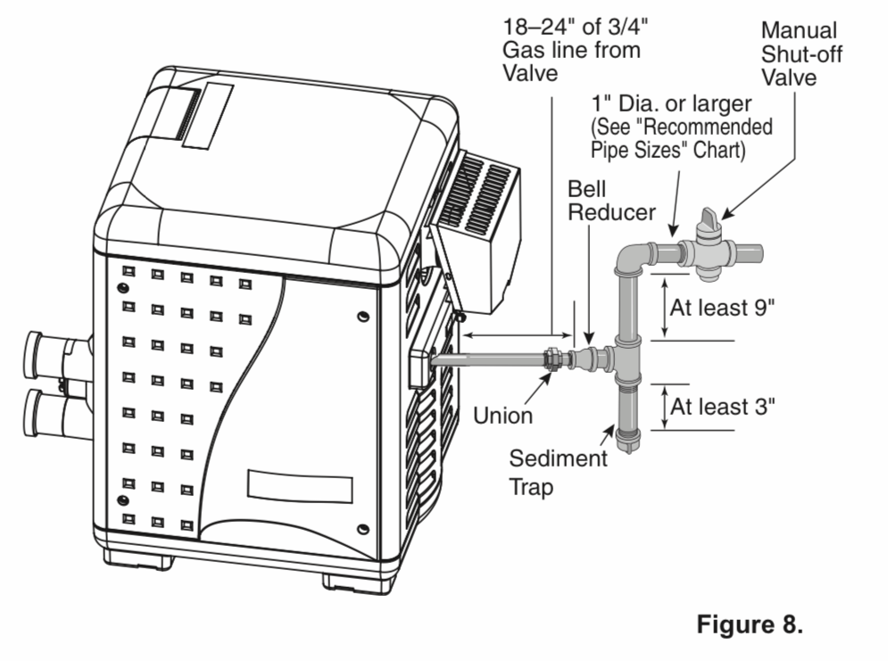
It looked like your sediment trap may be installed incorrectly. It was hard to see while you waved the camera around.

Sediment can clog the gas valve.

Gas_Heater_Sediment_Trap.png
 
Last edited:
  • Like
Reactions: wireform
Show the bypass valve.

Check the Flame Current.

The red LED looks like it might be on solid, which is a Control Fault.

Can you confirm?

1740616045661.png

Testing the Flame Sense Circuit.​

The Fenwal has two test points for flame current FC+ and FC-. Flame current is the current that passes through the flame from sensor to ground.

The best way to measure the flame sense current is with a true RMS meter. Measure the current with a good true rms meter that can measure dc current in the microamp range.

To measure flame current, connect a True RMS or analog DC micro-ammeter to the FC+ and FC- terminals. Readings should be 1.0 µA DC or higher. If the meter reads negative or below "0" on scale, meter leads are reversed. Reconnect leads with proper polarity.

If you don't have a RMS meter you can just test for voltage between FC+ and FC- terminals to confirm if you have flame sense. Each micro-amp of flame current produces 1.0 VDC. For example, 2.6 VDC equates to 2.6 µA. Voltage is an indirect indication but easier to do with typical DIY equipment. But it's still very difficult to measure unless you make up some pin wires to clip your voltmeter to. Or you can order some insulated micro clips for the test.

The reading should be 3-8 volts and this corresponds to the millionth's of an amp signal your flame sense signal should reading. If you try to check this be very careful since you can easily short the 24 vac circuit which can blow the transformer before the 2 amp fuse blows.

When not operating, the flame current should read 0 volts dc and 0 microamps dc. DC amps and voltage should be zero when there is no flame.

IMG_8031.JPEG
 
Show the bypass valve.

Check the Flame Current.

The red LED looks like it might be on solid, which is a Control Fault.

Can you confirm?

View attachment 629920

Testing the Flame Sense Circuit.​

The Fenwal has two test points for flame current FC+ and FC-. Flame current is the current that passes through the flame from sensor to ground.

The best way to measure the flame sense current is with a true RMS meter. Measure the current with a good true rms meter that can measure dc current in the microamp range.

To measure flame current, connect a True RMS or analog DC micro-ammeter to the FC+ and FC- terminals. Readings should be 1.0 µA DC or higher. If the meter reads negative or below "0" on scale, meter leads are reversed. Reconnect leads with proper polarity.

If you don't have a RMS meter you can just test for voltage between FC+ and FC- terminals to confirm if you have flame sense. Each micro-amp of flame current produces 1.0 VDC. For example, 2.6 VDC equates to 2.6 µA. Voltage is an indirect indication but easier to do with typical DIY equipment. But it's still very difficult to measure unless you make up some pin wires to clip your voltmeter to. Or you can order some insulated micro clips for the test.

The reading should be 3-8 volts and this corresponds to the millionth's of an amp signal your flame sense signal should reading. If you try to check this be very careful since you can easily short the 24 vac circuit which can blow the transformer before the 2 amp fuse blows.

When not operating, the flame current should read 0 volts dc and 0 microamps dc. DC amps and voltage should be zero when there is no flame.

View attachment 629918
Did you find that picture from my post a year ago? That’s the bypass for the heater
 
  • Like
Reactions: JamesW
Show the bypass valve.

Check the Flame Current.

The red LED looks like it might be on solid, which is a Control Fault.

Can you confirm?

View attachment 629920

Testing the Flame Sense Circuit.​

The Fenwal has two test points for flame current FC+ and FC-. Flame current is the current that passes through the flame from sensor to ground.

The best way to measure the flame sense current is with a true RMS meter. Measure the current with a good true rms meter that can measure dc current in the microamp range.

To measure flame current, connect a True RMS or analog DC micro-ammeter to the FC+ and FC- terminals. Readings should be 1.0 µA DC or higher. If the meter reads negative or below "0" on scale, meter leads are reversed. Reconnect leads with proper polarity.

If you don't have a RMS meter you can just test for voltage between FC+ and FC- terminals to confirm if you have flame sense. Each micro-amp of flame current produces 1.0 VDC. For example, 2.6 VDC equates to 2.6 µA. Voltage is an indirect indication but easier to do with typical DIY equipment. But it's still very difficult to measure unless you make up some pin wires to clip your voltmeter to. Or you can order some insulated micro clips for the test.

The reading should be 3-8 volts and this corresponds to the millionth's of an amp signal your flame sense signal should reading. If you try to check this be very careful since you can easily short the 24 vac circuit which can blow the transformer before the 2 amp fuse blows.

When not operating, the flame current should read 0 volts dc and 0 microamps dc. DC amps and voltage should be zero when there is no flame.

View attachment 629918
Another thing I thought of is this could have been setup for natural gas originally. What would need to be changed going to propane?
 

Enjoying this content?

Support TFP with a donation.

Give Support
Thread Status
Hello , This thread has been inactive for over 60 days. New postings here are unlikely to be seen or responded to by other members. For better visibility, consider Starting A New Thread.