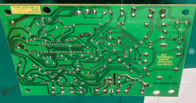
SPA heater, what would happen?

The board was just an example used earlier for example.

Ignore the red arrow.

See if the relay is getting 24 volts DC.

If the relay is getting 24 volts DC and not closing, then the relay is bad.

If the relay is not getting 24 volts DC, then the relay driver might be bad or the main circuit board might be bad.
Thanks @JamesW.

I will take a look to the relays and resistors and let you know (at least, about the relays).

In case of board replacement, any suggestion where to buy? I look at amazon, and see various kinds of devices. For example, the one who says are the same part number and the one who says are exact replacement (less expensive). In any case, the reviews show they received either device.
 
In case of board replacement, any suggestion where to buy? I look at amazon, and see various kinds of devices. For example, the one who says are the same part number and the one who says are exact replacement (less expensive). In any case, the reviews show they received either device.

Members have mixed experiences getting non-Pentair knockoff boards from Amazon or eBay sellers. Some worked and many did not. Be prepared to return it if it does not work 100%.
 
  • Like
Reactions: Hulaomr
When replacing the Fenwal, make sure you get the exact model number. The models are specific to heaters.
 
  • Like
Reactions: Hulaomr
By chance, anybody have the circuit schematic of the Fenwal board? Considering the time it takes me to received a new one, I will troubleshoot it further in the lab.
 
The two black boxes are relays.

The top box is probably the blower relay.

The black box on the right might be the valve relay.

The blue box might be the ignitor relay.

1734649383518.png
1734649363235.png
 
Last edited:
Once the blower pressure switch is closed, you should get 24 volts AC from TH to Ground, which is what closes the relay that powers the ignitor.

L1 closes to S1 and L2 closes to S2.

If the power supply is 240 VAC, the Fenwal ICM has to convert the 240 volts to 120, so L1 cannot close directly to the (240) S1.

On a call for heat, the blower and HSI (Hot Surface Ignitor) are energized.

The HSI should receive 120 volts when you hear the blower start.

If the main supply voltage going to the heater is 120 volts, then the voltage reading to the HSI should be a clean 120 volts.

If the power to the heater is 240 volts, the voltage sent to the HSI is an intermittent pulse that "simulates" 120 volts.

The intermittent pulse will not read as a clean voltage by a multimeter.

A true RMS will get a better read on the voltage, but the voltage might read higher or lower than exactly 120 volts.

In about 20 seconds, the gas valve opens and ignition should occur.

1734652053560.png

If your heater is correctly connected to 240 Volts AC, the Ignition Control Module (ICM) will convert the 240VAC to an intermittent pulse to the ignitor.

Digital meters don’t read this type of signal well.

(An analog meter will give a better reading than a digital meter).

If the ICM is bad, your voltmeter will read either 0 VAC or 240 VAC.

If your ICM is good, your meter will read some voltage between 0 and 240 VAC.

Exactly what reading you get will depend on the meter, but with a good ICM, the reading won’t be 0 VAC or 240 VAC, but somewhere in between.

1734653021093.png


Attachments

  • Heater-PentairMastertemp.pdf
    3.7 MB · Views: 0
Last edited:
Once the blower pressure switch is closed, you should get 24 volts AC from TH to Ground, which is what closes the relay that powers the ignitor.
The control voltage is 24 VAC, but the relays are 24 VDC, so the 24 VAC is not directly driving the relays.

The relays are driven by the relay driver.

See if you have 24 VAC at the TH terminal to GND.

If yes, then the relay should be closing.

If no voltage at TH to GND, then the main circuit board might be bad.

If you have 24 VAC at TH to GND, then maybe the relay or relay driver are bad.

The relay driver is cheap and an easy fix if you want to try that.

I an pretty sure that this relay driver will work, but not 100% sure.


Can you see a part number on the blue box?

1734654214997.png

1734654092605.png
 
Last edited:
The blower (Inducer) starts when 24 VAC is sent to the IND (Inducer) terminal. Verify 24 VAC from IND to GND. This closes the F1 to F2 relay.

Once the blower pressure switch closes, 24 VAC is sent to the TH terminal. Verify 24 VAC from TH to GND. This closes the L1 to S1 and L2 to S2 relay to power the ignitor with 120 volts.

The gas valve opens when 24 VAC is sent to the VAL terminal at about 20 seconds after the ignitor is powered.

It seems like the blower and gas valve relays are working, but the ignitor relay is not working.

If you are getting 24 VAC at the TH to GND you might be able to replace the relay driver or relay or get a whole new Fenwal.

If you are not getting 24 VAC from TH to GND, then we can look at the main circuit board.

1734656422086.png
 

Enjoying this content?

Support TFP with a donation.

Give Support
Note that the board is labeled as being Not Repairable.

No repairs are recommended or even suggested.

The recommended repair is to replace the Fenwal if it is defective.

Any repairs are at your own risk based on your own research.

All information provided is for research purposes only.

1734658327950.png
 
The control voltage is 24 VAC, but the relays are 24 VDC, so the 24 VAC is not directly driving the relays.

The relays are driven by the relay driver.

See if you have 24 VAC at the TH terminal to GND.

If yes, then the relay should be closing.

If no voltage at TH to GND, then the main circuit board might be bad.

If you have 24 VAC at TH to GND, then maybe the relay or relay driver are bad.

The relay driver is cheap and an easy fix if you want to try that.

I an pretty sure that this relay driver will work, but not 100% sure.


Can you see a part number on the blue box?

View attachment 621875

View attachment 621873
@JamesW, the blue relay is SMI-S-224L


1734969415517.png
1734969429019.png
 
  • Like
Reactions: JamesW
Once the blower pressure switch is closed, you should get 24 volts AC from TH to Ground, which is what closes the relay that powers the ignitor.

L1 closes to S1 and L2 closes to S2.

If the power supply is 240 VAC, the Fenwal ICM has to convert the 240 volts to 120, so L1 cannot close directly to the (240) S1.

On a call for heat, the blower and HSI (Hot Surface Ignitor) are energized.

The HSI should receive 120 volts when you hear the blower start.

If the main supply voltage going to the heater is 120 volts, then the voltage reading to the HSI should be a clean 120 volts.

If the power to the heater is 240 volts, the voltage sent to the HSI is an intermittent pulse that "simulates" 120 volts.

The intermittent pulse will not read as a clean voltage by a multimeter.

A true RMS will get a better read on the voltage, but the voltage might read higher or lower than exactly 120 volts.

In about 20 seconds, the gas valve opens and ignition should occur.

View attachment 621866

If your heater is correctly connected to 240 Volts AC, the Ignition Control Module (ICM) will convert the 240VAC to an intermittent pulse to the ignitor.

Digital meters don’t read this type of signal well.

(An analog meter will give a better reading than a digital meter).

If the ICM is bad, your voltmeter will read either 0 VAC or 240 VAC.

If your ICM is good, your meter will read some voltage between 0 and 240 VAC.

Exactly what reading you get will depend on the meter, but with a good ICM, the reading won’t be 0 VAC or 240 VAC, but somewhere in between.

View attachment 621868


The voltage in TH and GND is as expected (25Vac).

1734970549560.png
 
The blower (Inducer) starts when 24 VAC is sent to the IND (Inducer) terminal. Verify 24 VAC from IND to GND. This closes the F1 to F2 relay.

Once the blower pressure switch closes, 24 VAC is sent to the TH terminal. Verify 24 VAC from TH to GND. This closes the L1 to S1 and L2 to S2 relay to power the ignitor with 120 volts.

The gas valve opens when 24 VAC is sent to the VAL terminal at about 20 seconds after the ignitor is powered.

It seems like the blower and gas valve relays are working, but the ignitor relay is not working.

If you are getting 24 VAC at the TH to GND you might be able to replace the relay driver or relay or get a whole new Fenwal.

If you are not getting 24 VAC from TH to GND, then we can look at the main circuit board.

View attachment 621891
@JamesW as you mentioned, the ignitor relay is not working. I remove it and tested with a power supply (24VDC@100mA) and not current neither contact switching happened. It seems the internal coil is damaged.

I will check the voltage on the board to be sure is powering the relay coil.

1734971097845.png
 
  • Like
Reactions: JamesW
The voltage in TH and GND is as expected (25Vac).
I suspect that the relay driver or the relay is bad.

You can check the coil resistance.

The Coil Resistance is listed as 1067 Ω.

You can try replacing the relay and/or relay driver if you want, but I cannot recommend these repairs.

Only you can decide if you want to try the repairs or buy a new Fenwal.

I am not sure exactly how the board converts power from 240 to 120 VAC to the ignitor.

If you are getting 24 VAC at TH to GND and no voltage to the ignitor, then that points to a defect somewhere on the Fenwal.


Manufacturer. SANYOU

Type of relay. electromagnetic

Contacts configuration. DPDT

Rated coil voltage. 24V DC

Contact current max. 8A

AC contacts rating @R (at resistive load) at resistive load 8A / 277V AC

Relay series. SMI

Switched voltage. max. 277V AC

Relay variant. miniature

Mounting. THT

Coil resistance. 1067Ω

Coil voltage min. 18V DC

Coil voltage max. 31.2V DC

Body dimensions. 29.2x12.8x20.6mm

Coil power consumption. 540mW

Operating temperature. -40...85°C

Contact resistance. 100mΩ

Contact material. AgSnO2

Current rating. 8A

Switching capacity. 2216VA
 
Last edited:
I suspect that the relay driver or the relay is bad.

You can check the coil resistance.

The Coil Resistance is listed as 1067 Ω.

You can try replacing the relay and/or relay driver if you want, but I cannot recommend these repairs.

Only you can decide if you want to try the repairs or buy a new Fenwal.

I am not sure exactly how the board converts power from 240 to 120 VAC to the ignitor.

If you are getting 24 VAC at TH to GND and no voltage to the ignitor, then that points to a defect somewhere on the Fenwal.


Manufacturer. SANYOU

Type of relay. electromagnetic

Contacts configuration. DPDT

Rated coil voltage. 24V DC

Contact current max. 8A

AC contacts rating @R (at resistive load) at resistive load 8A / 277V AC

Relay series. SMI

Switched voltage. max. 277V AC

Relay variant. miniature

Mounting. THT

Coil resistance. 1067Ω

Coil voltage min. 18V DC

Coil voltage max. 31.2V DC

Body dimensions. 29.2x12.8x20.6mm

Coil power consumption. 540mW

Operating temperature. -40...85°C

Contact resistance. 100mΩ

Contact material. AgSnO2

Current rating. 8A

Switching capacity. 2216VA

The resistance reading are not as expected (>50MOhn)

1734972642102.png
 
@JamesW as you mentioned, the ignitor relay is not working. I remove it and tested with a power supply (24VDC@100mA) and not current neither contact switching happened. It seems the internal coil is damaged.

I will check the voltage on the board to be sure is powering the relay coil.

View attachment 622103
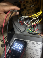
@JamesW the voltage at the coil relay (during operation) is around 35VDC (open circuit) during 20 seconds. It repeats multiple times during the starting. Its look the board is working as expected and the only issue is the relay.

I will try to source/buy the relay locally to try.

1734972798214.png
 
Last edited:
  • Like
Reactions: JamesW

Enjoying this content?

Support TFP with a donation.

Give Support
Thread Status
Hello , This thread has been inactive for over 60 days. New postings here are unlikely to be seen or responded to by other members. For better visibility, consider Starting A New Thread.