VS pump consumption measurements, I'm getting a weird result

Pierrot

Active member
Jan 18, 2024
38
San diego
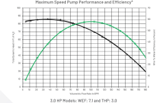
I was curious to see how much power my VSP uses as different speeds. I measured the power with a clamp meter and got the results below.
As you can see, there is a drop at around 1500rpm. It means that my pump uses less energy to run at 1600 rpm than it does at 1500 rpm. It doesn't make any sense to me.
I performed several measurements at each speed, and always get the same shape.

Is there a physical explanation to this, or is it more likely that my clamp meter is somehow malfunctioning?
Capture d’écran 2024-06-16 à 15.54.00.png
 
Is there a physical explanation to this, or is it more likely that my clamp meter is somehow malfunctioning?
Do you have any check valves in the system and/or a natural gas heater?. Both of these devices have springs in the flow path which can alter the power curve (as well as flow) of a VS pump. These devices do not always open smoothly so at certain flow rates open abruptly.
 
  • Like
Reactions: Bperry
What pump?

Does the pump show the power used?

What meter are you using?

Are you measuring power factor?

Are you using a wattmeter or an ammeter?

Is your meter True RMS?
 
Last edited:
Do you have any check valves in the system and/or a natural gas heater?. Both of these devices have springs in the flow path which can alter the power curve (as well as flow) of a VS pump. These devices do not always open smoothly so at certain flow rates open abruptly.
I do indeed have a natural gas heater. Good deduction!

What pump?

Does the pump show the power used?

What meter are you using?

Are you measuring power factor?

Are you using a wattmeter or an ammeter?

Is your meter True RMS?
It's a whisperflo 1.5HP. Yes the pump shows the power used, but I was curious to verify with my own measurements. When drawing the "power showed by the pump" curve, it has a similar shape, but the pump seems to under estimate how much power it uses at lower speed.
I'm using a clamp meter, it's measuring amperes and it's true RMS. I multiply by 240V to get the power in Watts.

> Are you measuring power factor?
I'm not sure what that means 😅

Capture d’écran 2024-06-17 à 08.52.27.png
 
Volt x amps = Apparent Power.

Apparent Power x Power Factor = True Power.

The apparent power in the below example is 16.97 x 245 = 4,157.65 volt-amps.

The True Power is 4,157.65 volt-amps x 0.89 (Power Factor) = 3.700 Kilowatts.

The pump drive has a power input and a power output.

The input is 240 volts single phase at 60 hz frequency.

The output is three-phase at the necessary frequency to rotate the shaft at the selected RPM.

The Drive might be measuring power at the input and/or the output.

You will not get the same exact power measurements at the input and the output.


1718637049453.png

1718636979857.png


I'm using a clamp meter, it's measuring amperes and it's true RMS. I multiply by 240V to get the power in Watts.
That is giving you volts-amps, which is apparent power and not true power.

The motor might be measuring input and/or output and it might be using true or apparent power.

The motor power factor might change at 1,600 RPM for some reason.

Maybe you have a low power factor at 1,500 RPM and it improves at 1,600 RPM.

The drive converts the input single phase AC power to DC power and then it creates a simulated digital 3 phase AC output using fast switches, which distorts the input power.
 
A variable frequency drive should have a power factor very close to 1 because of the isolation between the AC input, the DC conversion stage, and the PWM AC waveform going into the motor. The first stage of a VFD is an AC to DC converter and once AC is converted to DC, the power factor is undefined. Power factor is only defined for AC waveforms.

Even in the 3-phase motor, the 3-phase power factor can be managed to also be close to one by changing the duty cycle of the PWM waveform.


1718637870745.png

Some of the PWM harmonics could bleed back into the mains lines via RF coupling but that should be very tiny.

Also, I believe the reason the wattage is different between the measurement of the AC mains lines and the pump drive display is because the AC mains lines wattage includes the drive electronics while the display in VS drive is for the motor only. You can see how drive wattage goes close to zero while the input wattage levels out at around 100 watts and from the Energy Star measurements, the same thing happens. Most drives have an offset of around 100 watts due to the drive electronics.

The sharp change in the power curve is due to a change in the plumbing curve. Most likely the heater bypass valve opening further.
 

Enjoying this content?

Support TFP with a donation.

Give Support
Drive electronics are run off of DC so no power factor there.

Power factor is only relevant for AC waveforms directly running reactive loads. This is why you see it mostly in inductive motors and sometimes in transformers with AC loads.

A VFD has a DC circuit that separates the input AC from the motor PWM AC. The only way the motor can influence the input AC is via radio waves.

1718639761239.png

Also, this is why back EMF can destroy a VFD. The controller adjusts the PWM waveform to minimize the reverse current which in turn forces the power factor from the motor closer to 1.

Power factor is a measurement of reactive power. Reactive power is the VA used to establish the magnetic field in a motor. For permanent magnet motor, most time you see pf being unity, which means all VAs are used to generate torque (minus the loss, of course). Under the condition of field weakening operation though, you will see the PM motor gets less than unity pf because some VAs are used to counter the perm magnet field.
But this is the discussion of the PF in the PM motor not the input of the drive. The last part is for when the motor is underloaded but that can be corrected for as well in the PWM waveform.

Here is the comment on the input
Think of a VFD driving an induction motor. Strictly speaking, as the variable frequency drive does not cause any significant displacement of the voltage and current waveforms on its input it could be thought to have a displacement power factor of close to unity.

If I get a chance, I can show you the voltage and current waveforms on my pump drive. I think I did this once before but my memory is a bit foggy on this.
 
Theory is nice, but I would want to see actual True Power (Watts), Apparent Power (Volt-Amps) and Power Factor Measured for the drive input power and the drive output power at different speeds.

Also, I would want to see Vacuum and Discharge Pressure measurements and flow measurements for different speeds.
 
The sharp change in the power curve is due to a change in the plumbing curve. Most likely the heater bypass valve opening further.
If this is happening, then you should have a small but noticeable drop in filter pressure as the speed goes from 1,500 RPM to 1,600 RPM where the power used drops.

Actually, if there is less restriction, wouldn't the power used go up, not down?
 
  • Like
Reactions: mas985
When power is converted from AC to low voltage DC, there is definitely a power factor for the transformer.

The power factor on an ac to low voltage dc transformer is usually quite low.
In some cases but it depends on the type of AC/DC conversion that is done for the electronics.
 
@Pierrot, post a picture of your plumbing.

I would like to see if there is anything else in the plumbing whose plumbing curve may change with flow rate.
 
Actually, if there is less restriction, wouldn't the power used go up, not down?
With increasing RPM, the power should go up anyway and yes from there if there was less head loss, the power should go up slightly. But we don't know what may be going on in the plumbing so head loss may be increasing due to something in the plumbing. It is a pretty big change and would require a pretty large change in the plumbing curve so it should be seen by the filter.

Using my pump model, it looks like the plumbing curve would need to triple to get that kind of change. Sounds more like a broken check valve.

Another possibility is that the drive is doing something different at higher RPM vs lower RPM to improve efficiency. But I have not seen this effect before on any other VS pump where multiple measurements were made.
 
  • Like
Reactions: JamesW

Enjoying this content?

Support TFP with a donation.

Give Support
Thread Status
Hello , This thread has been inactive for over 60 days. New postings here are unlikely to be seen or responded to by other members. For better visibility, consider Starting A New Thread.