Installing Circupool RJ45

dank0050

Gold Supporter
Apr 14, 2024
23
Gilbert, AZ
Pool Size
13000
Surface
Plaster
Chlorine
Salt Water Generator
SWG Type
CircuPool RJ-45
My RJ45 will be arriving in a few days.

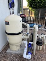
1)bought the vertical kit and plan to install it horizontally as I have very limited space 12” or so to work with and the inlet is right above. Any other ideas on where/how to install given my setup?

2)Will have the cell oriented with the dip pointing down (VS pump). Flow switch on one arm of the U before the unit on the other arm. Will i need to add a support for the horizontally placed U?

Will be going out of town for 5 days a week from today. Would love to have this up and running by the end of the week, doable?

I’ll add a follow up to this post for the electrical install. Thanks for your help!
 

Attachments

  • IMG_2646.jpeg
    IMG_2646.jpeg
    691 KB · Views: 44
  • IMG_2647.jpeg
    IMG_2647.jpeg
    517 KB · Views: 38
Last edited:
2)Will have the cell oriented with the dip pointing down (VS pump). Flow switch on one arm of the U before the unit on the other arm. Will i need to add a support for the horizontally placed U?
Yes I would put a support under the horizontal U. Buy an extra 2” or 3” Tee and cut it in half so it becomes a cradle for the plumbing. Put a straight piece of pipe down to the ground.
 
  • Like
Reactions: dank0050
Can you confirm what all the return lines are for? The smaller 1/4" lines, are those for water features? Then the two larger 2" lines, return jets, or also spa perhaps? Maybe a larger water feature?
From left to right of filter: water feature, aerator, infloor cleaning / blue return valve labeled fixed nozzle (wall returns or deck chlorinator?)
 
Last edited:
Think I should have enough pipe for the horizontal U?
 

Attachments

  • IMG_2757.jpeg
    IMG_2757.jpeg
    643.9 KB · Views: 22
  • IMG_2758.jpeg
    IMG_2758.jpeg
    489.1 KB · Views: 21
Last edited:
From left to right of filter: water feature, aerator, infloor cleaning / blue return valve labeled fixed nozzle (wall returns or infloor chlorinator?)
I was curious what that 1/4” return line was for labeled fixed nozzle. I opened it all the way and this in deck chlorinator/tab feeder started overflowing with water
 

Attachments

  • IMG_2760.jpeg
    IMG_2760.jpeg
    755.5 KB · Views: 13
Last edited:
@HermanTX @Texas Splash - thanks for your responses to this thread. So I did some more detailed measuring and I have 9” of pipe between the filter union end and the union for the 90 degree. This is the pipe I’m planning to cut in for a horizontal U to make room for the cell and flow switch. The U kit from Circupool calls for a 6.5” gap. I’m assuming then I would need 1.5” of pipe on each side of the gap so 9.5” total. As mentioned I have 9” to work with. Will only seating the pipe 1.25” vs 1.5” matter?

The other option I’ve considered is scrapping the U and installing the cell directly on my pipe running down underground and back up to the IF cleaning manifold. This would have plenty of room for the cell and flow switch but the switch would be on a downflow. The only other place I could put the switch is on that same 9”horizontal pipe coming out of the filter but having switch before diverter and cell after seems like a very bad idea.

IMG_2647.jpeg
So stick to my plan with the horizontal U (blue in pic) or have both switch and cell on down flow pipe leading to IF cleaning manifold (green in pic) ?
 
Last edited:
The green pipe is to the right of the 3-way valve - where does the pipe to the left of the 3-way valve go?
If the SWCG is set before the 3-way valve then both pipes will have chlorinated water going to them.

Check with the mfg but flow switch should be horizontal or on the upwards flow pipe if vertical install. If you put SWCG on green pipe and flow switch on the horizontal pipe before the 3-way valve, it would register flow if going to the left pipe but the SWCG is on the right (green) pipe. That is not a good idea.

On the vertical section of the pipe coming from the filter - there is a Tee before the 3-way valve. That Tee connects to a small diameter pipe - what does that flow to?
 
On the vertical section of the pipe coming from the filter - there is a Tee before the 3-way valve. That Tee connects to a small diameter pipe - what does that flow to?
Aerator
The green pipe is to the right of the 3-way valve - where does the pipe to the left of the 3-way valve go?
water features.
 
Last edited:

Enjoying this content?

Support TFP with a donation.

Give Support
Flow switch needs to be in the vertical pipe with upward water flow. That way when (not if - when) the flow switch fails, it will still not allow the SWG to come on without flow.
The cell can be in the up or down pipe.

Or you can go horizontal - in the direction opposite your pool pump - toward the side of the filter we can't see in the pic.

Post pictures from the opposite side of the filter and and also looking dead on to the 3-way valve (show pump amd dilter in that frame. This will help determine other options you may have.

You will also need a timer that the SWG is wired to. This allows the SWG to only run within the time the pump runs. The timer should be set to power the SWG on 30 minutes after the pump comes on and power the SWG off 30 minutes before the pump turns off. The timer is the primary safety device, the flow switch is the secondary safety device.
 
Flow switch needs to be in the vertical pipe with upward water flow. That way when (not if - when) the flow switch fails, it will still not allow the SWG to come on without flow.
The cell can be in the up or down pipe.

Or you can go horizontal - in the direction opposite your pool pump - toward the side of the filter we can't see in the pic.
This was my original plan (horizontal U) but I only have 9” of pipe between the filter and the 90. I think I need 9.5” of pipe for the U: 6.5” gap plus 1.5” on either side to fully insert into the unions of the U.
Post pictures from the opposite side of the filter and and also looking dead on to the 3-way valve (show pump amd dilter in that frame. This will help determine other options you may have.
Will do.
You will also need a timer that the SWG is wired to. This allows the SWG to only run within the time the pump runs. The timer should be set to power the SWG on 30 minutes after the pump comes on and power the SWG off 30 minutes before the pump turns off. The timer is the primary safety device, the flow switch is the secondary safety device.
You have been a great help on my other thread discussing the electrical side of the install. Thank you.
 
This was my original plan (horizontal U) but I only have 9” of pipe between the filter and the 90. I think I need 9.5” of pipe for the U: 6.5” gap plus 1.5” on either side to fully insert into the unions of the U.

Will do.

You have been a great help on my other thread discussing the electrical side of the install. Thank you.
 

Attachments

  • IMG_2773.jpeg
    IMG_2773.jpeg
    510.6 KB · Views: 21
  • IMG_2774.jpeg
    IMG_2774.jpeg
    588.9 KB · Views: 21
  • IMG_2775.jpeg
    IMG_2775.jpeg
    622.2 KB · Views: 21
This was my original plan (horizontal U) but I only have 9” of pipe between the filter and the 90. I think I need 9.5” of pipe for the U: 6.5” gap plus 1.5” on either side to fully insert into the unions of the U.
I think the horizontal idea will work. I looked at the loop and it is only 6.5" from edge of the elbows.
If you cut out the middle of that horizontal pipe you can glue in those elbows individually and then work across to the flow switch and SWCG. Then the final U (the end cap of 2 elbows and a straight between them can be glued all at once.
The only important part is to have unions on the actual SWCG to remove it.

Go buy 2 elbows at Home Depot and place them on the existing horizontal pipe such that the ends are 6.5" apart. I think you will see it will work.
 
I sure hope some pics are coming. Curious to see the final work.


Not perfect. There was some trial & error with plumbing in the horizontal U and some rookie mistakes (ie priming the outside of the cell unions 🤦‍♂️). Now I need to paint. Thinking Almond Rustoleum?
 

Attachments

  • IMG_2792.jpeg
    IMG_2792.jpeg
    793.3 KB · Views: 37
  • IMG_2790.jpeg
    IMG_2790.jpeg
    722.2 KB · Views: 35
  • IMG_2794.jpeg
    IMG_2794.jpeg
    540.4 KB · Views: 34
  • Like
Reactions: Rancho Cost-a-Lotta
Not perfect. There was some trial & error with plumbing in the horizontal U and some rookie mistakes (ie priming the outside of the cell unions 🤦‍♂️). Now I need to paint. Thinking Almond Rustoleum?
Great work. I would do 1 more thing. Add a brace at the top of the horizontal U. Buy either a 2” or 3” T (use DWV fitting as cheaper) and a short piece of pipe. Cut the T in half such that the hole is on one side. Put the pipe in it and put the half moon T under the end to brace it.
 

Enjoying this content?

Support TFP with a donation.

Give Support
Thread Status
Hello , This thread has been inactive for over 60 days. New postings here are unlikely to be seen or responded to by other members. For better visibility, consider Starting A New Thread.