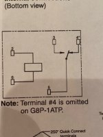
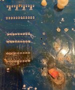
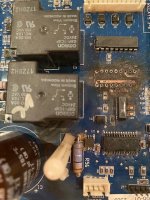
I removed u4 which was not easy because it was like a piece of charcoal that crumbled. So I had to snip each lead and solder suck the remnants out. Under the u4 the board was superficially charred in some places and not so superficially charred in others. There appears to be a fair amount of connectivity of the u4 to the U5 so some of the traces survived. Some have continuity and others don't with the U4 but without a schematic I am left guessing if that is by design or by fate. As mentioned before the K2 is charred below. The largest terminal on the k2 is fried and so is the largest terminal on the K1 but this happened previously. Update. Multimeter testing results. On k2 without U4 there is no continuity between terminals 2 and 6 (refer to image 1 the omron diagram).
There is continuity between 5 and 4 and 5 and 3 and also (of course) 3 and 4. On K3 there is low resistance between 2 and 6. The rest of the findings are the same ie 5 and 4, 5 and 3, 3 and 4, all have continuity. K 1 coil has low resistance ie 2,6. 5 has continuity with 4 but not 3 and 3 and 4 have no continuity.