Heater Bypass - how to install in this scenario

pbc

Well-known member
Jun 26, 2018
183
Toronto, Canada
Pool Size
15000
Surface
Vinyl
Chlorine
Salt Water Generator
SWG Type
Hayward Aqua Rite (T-9)
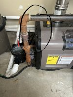
So looks like I need to replace my Hayward H250FDN heat exchanger and or the whole heater as it’s leaking.

Thinking while I’m at it I would install a bypass so that I don’t need to run water through the heater every time the pump runs.

Read the bypass thread here Heater Bypass - Further Reading

I also have a ProLogic PL4, but not sure I can hook up an automated control valve since both Aux buttons are used (lights and waterfall pump)?

Also, looking at the existing install, it’s pretty tight where the SWG is. Am I still able to plump in a bypass?

Wish I had read up on this when the pool was first installed!

BE27DB40-1F0E-4397-94E3-EC76F2E0E070.jpeg

BACB0222-E2F9-4CDA-9D29-70617A4EAD60.jpeg

61D73C58-C6F6-4D0D-B0F8-E0778CB4203E.jpeg
 

Attachments

  • F59E6A04-F550-4698-A7C6-C8AAEF3536CC.jpeg
    F59E6A04-F550-4698-A7C6-C8AAEF3536CC.jpeg
    463.9 KB · Views: 50
Eagle eye! Thanks, probably put it on backwards when I was cleaning it yesterday in a rush.

Any thoughts on how I would plumb a bypass given where the cell is located in the path?

Probably will just get my pool guy to do it but not 100% sure how many he’s done so want to make sure it is done right.
 
Actually, looking at an earlier post before I left for vacay I likely put in on backwards as I was taking it on and off trying to trouble shoot a leak from the heater.
 
  • Like
Reactions: JamesW
Okay, trying to read up as much as I can, but struggling a bit to figure out how best to put in the bypass (or instruct the pool guy to, as I'm not sure he's done them before).

In the pic below, you can see my salt water cell is plumbed almost directly into the check valve and then into the heater, which I think creates a bit of a PIA for inserting a bypass now.

What I'm thinking is:

1. Pick up a kit like this , though I think I need a 90 degree check valve?
2. Move the salt cell over to the position where the flow switch is currently sitting (though unless I'm mistaken, do I then need to purchase a new flow switch??)
3. Move the flow switch over to where it says pipe 1
4. Somehow plumb the diverter valve into the pipe 2 location so that it can either send into the heater or sent to the cell?

But basically am I looking at needing to buy another new check valve and flow switch and some complicated re-routing? Ugh.


1661185289206.png
 
Not sure if this pic helps. But staring at it a bit more, something along these lines. Basically move the T cell to the top, flow switch to the side (in the pic above move to where it says "Pipe 1"), diverter at the bottom (pipe 2 in the original pic above). One new pipe coming up from the diverter valve into a 90 degree fitting that goes into a T fitting / new pipe just above the existing check valve (where in the above pic the salt cell currently sits).

Would that work?

1661188296966.png
 
I think I can cut the flow switch out and use couplings to reuse it, and may be able to use the existing check valve vs having to purchase a new one? Just not sure I will have enough "pipe" on one side of the flow switch to attach a coupling as it looks like it will only be about an inch?
 
The flow switch should not be installed a vertical pipe that has downflow of water as gravity can cause the flow switch to fail in a closed position.

Put the cell horizontal and the flow switch on pipe 3 which has the upflow
 
The flow switch should not be installed a vertical pipe that has downflow of water as gravity can cause the flow switch to fail in a closed position.

Put the cell horizontal and the flow switch on pipe 3 which has the upflow

So more like this? The length of the top pipe isn't enough to fit both the cell and the flow switch, unless I can angle the pipe coming up from the heater a bit more under the vent and use a 45 degree.

Probably easier to look at it right side up!

1661195900064.png
 

Enjoying this content?

Support TFP with a donation.

Give Support
Or have a 90 coming out of the check valve going to the right, then a vertical stack just below the the external vent, to add some extension on the top piece.

I know with electrical runs of certain gauges you can't have too many 90's by code (due to heat build up etc), this is obviously not an electircal run, but any issues with too many 90's in this sort of pool plumbing in terms of water flow issues?
 
The 3 way diverter goes onto the heater input pipe.

From the heater output union, stack the check valve, then the T that the 3 way connects to, then the flow switch. I would just take that U up higher if you need more room in the pipe to stack it all.

Ther eare no limits to the number of 90s in the plumbing but the fewer the better.

Yes, Pipe 2 would be the pipe where my poorly depicted picture was meant to show the diverter valve going, which would be the heater input pipe.

Bear with me, not following entirely, as I assume when you say "then the flow switch", you don't mean on the vertical pipe where the check valve is currently on.

For the PVC coming out of the heater and into the check valve and then the cell....do you mean make that pipe longer/higher. So that I leave the check valve where it is, then have a piece of pipe and T, then continuing up verticall the T is connected to the salt cell vertically. Then essentially the flow switch remains where it is now, just higher up?

Actually, this would work a lot better if it's what I'm thinking, assuming the pipe touching the vent isn't a huge issue. As I could reuse everything (would need to see if the existing check valve is glued on or screwed on).

I don't need a second check valve correct? Just leave the existing one where it is (as per the first photo way above), then insert a piece of pipe going up attached to a T, on the vertical just above the T I have the Salt water cell.

Excuse my Tetris pic below. But I think this would work?


1661199770437.png
 
You could do that.

What I was describing flipped the position of the SWG and flow switch.

Flow switch at the top of the vertical upflow pipe.

Cell on the horizontal run.

Either will work. Whichever fits better. The flow switch vertical does not take the piping as high.

1661200457358-png.448546
 
Ah, I see what you mean. I thought maybe the flow switch had to be "after" the cell, but I guess not. I think the one I drew up above would a much easier hack, my concern is that I will have to cut out the flow switch, and as you can probably see on the right side of it there is only 3/4" to an inch of pipe, and not sure that is enough pipe to add a coupling to?

I think in terms of parts, I just confirming I think I would need:

Diverter Valve - this one? Not sure what the differences are outside of the pipesize.

T PVC Fitting

90 Degree Elbow

Additional length of PVC pipe

Pipe might be 2" vs 1.5" now that I think about it so will confirm that and adjust accordingly. I don't think a Check Valve is needed as there is already one in the chain at the back of the gas heater?
 
Hayward is not as greedy as Jandy.

Good to know. Everyone seems to go with Jandy so was curious.

Not sure if this is a snag, but looking at the cell I am not sure how easy it will be to E018F313-B428-42B0-86CD-A326ED71CF64.jpegdisconnect this thing as it looks like the end near the check valve doesn’t have much pipe.
 

Enjoying this content?

Support TFP with a donation.

Give Support
Thread Status
Hello , This thread has been inactive for over 60 days. New postings here are unlikely to be seen or responded to by other members. For better visibility, consider Starting A New Thread.