No green lights

jrbevis

Active member
Sep 7, 2021
38
Las Vegas, Nv.
Pool Size
8000
Surface
Plaster
Chlorine
Salt Water Generator
SWG Type
Pentair Intellichlor IC-20
Hello,
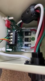
I had my IC-20 installed today and I have questions about the green lights..

The only way to get the green lights to illuminate is to have Super Chlorination on. They will all be lit up.

As soon as I have super turned off, all the lights turn off. On Screenlogic I have my pool output to 100%. The Green lights on the IC-20 do not light up. I can change to any percentage, and the green lights still won't light up.

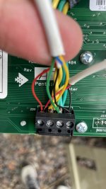
Also, the buttons on the IC-20 won't allow me to adjust sanitation levels. I presume this is because I'm supposed to control that with my phone?

What am I doing wrong?
Thanks
 
jr,

I suspect that your cell is not connected to your IntelliTouch.

Do you have an External SWCG power center?

If so, it has to be connected to com port of your IntelliTouch.

If your installer failed to connect the com cable, then there a good chance he did not connect the AC input to the cell correctly.

Put the system into the Service mode and then see if you can still get lights in the boost mode. If you have any lights in the Service mode, the power center is not correctly wired.

Show us some pics of your new install.

Thanks,

Jim R.
 
Hi Jim,
Yes, I have a power center.
I put the system in service mode and all the green lights remained illuminated.
Attached are some pics.
 

Attachments

  • 1.jpg
    1.jpg
    261.1 KB · Views: 10
  • 2.jpg
    2.jpg
    266.3 KB · Views: 10
jr,

Good news and bad news..

The good news is that your power center appears to be wired into the IntelliTouch's com port.

The bad news is that your power center is not wired into the load side of your Pump/Filter relay, which is a requirement, not an option.

I suspect that the installer did not "enable" your IntelliChlor.

For an EasyTouch it is... Menu, Setting, IntelliChlor, Enable = yes. I am not sure what it is on your IntelliTouch, but it should be something very similar.

Show me a several pics of your cabinet where I can see the wiring and the Pump/Filter relay. It should be in the upper left.

Thanks,

Jim R.
 
Jim,
I appreciate your help on this matter but I figured it out. I wasn't giving the SWG enough time to adjust the green lights after I made a change on my phone.
I think my next concern coincides with the wiring issue you spoke of. If I turn my pool pump off, the SWG remains "on" but I'm reliant on the flow sensor to stop producing chlorine. I'd hate to have a flow sensor go bad and detect flow when there isn't any.
 

Attachments

  • IMG_0607.jpg
    IMG_0607.jpg
    345.2 KB · Views: 10
  • IMG_0606.jpg
    IMG_0606.jpg
    324.4 KB · Views: 9
  • IMG_0604.jpg
    IMG_0604.jpg
    328.4 KB · Views: 7
  • IMG_0603.jpg
    IMG_0603.jpg
    399 KB · Views: 7
  • IMG_0602.jpg
    IMG_0602.jpg
    418.1 KB · Views: 8
  • IMG_0601.jpg
    IMG_0601.jpg
    314.1 KB · Views: 10
jr,

Glad you got the output% worked out... :goodjob:

Should be an easy fix, but the first thing we need to do is figure out where your SWCG power center gets its voltage.

Is there a conduit between the power center and the automation? If so which conduit?

Thanks,

Jim R.
 
jr,

Glad you got the output% worked out... :goodjob:

Should be an easy fix, but the first thing we need to do is figure out where your SWCG power center gets its voltage.

Is there a conduit between the power center and the automation? If so which conduit?

Thanks,

Jim R.
Does this help?
 

Attachments

  • IMG_0609.jpg
    IMG_0609.jpg
    381.1 KB · Views: 7
  • IMG_0608.jpg
    IMG_0608.jpg
    466.1 KB · Views: 7
jr,

Yes, that helps a lot.

As you can tell, the Power center is getting constant AC power from the bottom circuit breaker.

You need to wire the Pump/Filter relay so that it interrupts that AC power source.

So, the 240 volts out of the breaker needs to be wired to the Line Side of the Pump/Filter relay. Then the Load side of the Pump/Filter relay needs to be connected to the two wires currently going to the Power Center.

The inside of the door shows a diagram of the relay. Basically, if you look at the relay pins from left to right, they are Line #1, Load #1, Line #2, and then Load #2.

Pretty simple to do, but if you don't feel comfortable doing it, then you need to find a friend, or get the installer back out to do it correctly.

The reason for wiring the Power Center to the Pump/Filter relay is that you do not want to rely on just the flow switch. Does not happen often, but cells can actually explode if left powered on with no or low water flow.

Please let me know if you have any questions.

Thanks,

Jim R.
 
Last edited:
jr,

Yes, that helps a lot.

As you can tell, the Power center is getting constant AC power from the bottom circuit breaker.

You need to wire the Pump/Filter relay so that it interrupts that AC power source.

So, the 240 volts out of the breaker needs to be wired to the Line Side of the Pump/Filter relay. Then the Load side of the Pump/Filter relay needs to be connected to the two wires currently going to the Power Center.

The inside of the door shows a diagram of the relay. Basically, if you look at the relay pins from left to right, they are Line #1, Load #1, Line #2, and then Load #2.

Pretty simple to do, but if you don't feel comfortable doing it, then you need to find a friend, or get the installer back out to do it correctly.

The reason for wiring the Power Center to the Pump/Filter relay is that you do not want to rely on just the flow switch. Does not happen often, but cells can actually explode if left powered on with no or low water flow.

Please let me know if you have any questions.

Thanks,

Jim R.
Thank you Jim,
Are you aware of a specific Youtube video or an actual picture of correct wiring? I can certainly study the diagram on the panel but I'd feel more comfortable if I could actually see it wired correctly. Also, I have three little breakers inside my panel that are visible without removing the panel, is there supposed to be a fourth for the SWG?
Thank you
Jeff
 
jr,

If you have an External SWCG power Center then it has its own fuse.

No offense, but if you can't understand the diagram on the door, it would be better to get a friend to help out. Much better to be safe than blow anything up.

Thanks,

Jim R.
 

Enjoying this content?

Support TFP with a donation.

Give Support
jr,

If you have an External SWCG power Center then it has its own fuse.

No offense, but if you can't understand the diagram on the door, it would be better to get a friend to help out. Much better to be safe than blow anything up.

Thanks,

Jim R.
Roger that.
Thank you
Jeff
 
Roger that.
Thank you
Jeff
Hi Jim,
Quick question..
The top circuit breaker is my filter pump breaker. Looking at the diagram it appears to me that the filter pump breaker and the SWG breaker should both be wired to the filter pump relay.

I don't have ANYTHING wired to the filter pump relay.

Thank you
Jeff
 

Attachments

  • 5.jpg
    5.jpg
    351.7 KB · Views: 2
jr,

If you have a single speed pump it would have to be wired to the Pump/Filter relay for it to work.

Your IntelliFlo gets constant AC power and is told to run by an RS-485 serial cable by the electronics in your IntelliTouch. Because of this, the IntelliFlo is NOT wired to the Pump/Filter relay.

The Pump/Filter relay must be used to power your SWCG, so that it only comes on when the IntelliTouch is telling the pump to run.

Go back and look at post #8.

Thanks,

Jim R.
 
Thread Status
Hello , This thread has been inactive for over 60 days. New postings here are unlikely to be seen or responded to by other members. For better visibility, consider Starting A New Thread.