Thank you ajw22 for all of the help! I know there's some love in that North Jersey snarkiness
")
There is light at the end of the tunnel please stay with me.
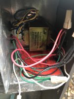
The heater was previously wired with the pump on the same 240V/20A circuit which was fed from the Tork timer. In the picture below, you can see the 3 WIRE connectors for BLACK/RED 240V and a GREEN that plug into the control box in the background. That's the direct power wiring, correct?! Those wires also extend through the heater to the conduit that feeds the pump. The new Intelliflow is now on a separate 240V breaker so I need to rewire the pump to remove it from the same circuit used by the heater assuming I am correct above and they are the ones powering the heater.
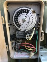
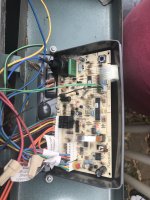
I reviewed the manual but I can't figure out the purpose of the connection between the Tork Timer's Fireman's switch into the furnace's control board (RIGHT 2 most pins on the block). The label says "WHEN NECESSARY ADD "FIREMANS" SWITCH CIRCUIT HERE DO NOT USE FOR REMOTE CONTROL CONNECTION. USE P8-SEE MANUAL" What is this? I've never seen "Clock/ Fireman Sw" on the control panel ever.
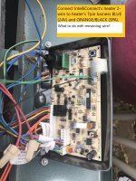
I believe I need to connect the IntelliConnect's HEATER to the 7-pin harness BLUE (24V) and ORANGE/BLACK (SPA) wires. Does this instruction " Attach wire nut on unused wire to the "Remote Interface Harness." refer to the OTHER wire (e.g. BLACK/ORANGE POOL WIRE) not being used? What does this mean??
Page 38 of manual (
https://www.royalswimmingpools.com/rp2100manual.pdf)
TIME CLOCK/FIREMAN’S SWITCH
To operate the heater with a time clock, connect the timer to the fireman’s switch connection in the heater’s wiring. The time clock should be of the dual switch type and set to shut off the call for heat to the pool heater 15 to 20 minutes prior to shutting down the pool pump. On millivolt heaters the fireman’s switch connection is a wire nut located in the Violet/Black wiring between the manual toggle switch and the gas valve. For AFT heaters the fireman’s switch connection is located on the 14-pin header connected to the digital control board. Splice into the red wire jumper tagged “Where necessary add “Fireman’s” switch circuit here” to connect the time clock. The fireman’s switch connection on both millivolt and AFT heaters must be a dry contact and must not supply power to the heater. Powering the fireman’s switch connection externally may damage the heater, and is not covered by warranty. Millivolt heaters: Do not exceed 15ft of total wiring using 14 AWG stranded copper wire rated for 105ºC (221ºF) minimum. AFT heaters: Do not exceed 50ft of total wiring using 18 AWG stranded copper wire rated for 105ºC (221ºF) minimum. NOTE: When using a time clock, the heater will display “Clock/ Fireman Sw” when the fireman’s switch is open, indicating that the time clock has shut off the call for heat.
2-Wire Remote Control (On-Off)
This application assumes that only one heating function (pool or spa) is required.
1. Turn on power to the heater.
2. For a 2-Wire Remote Control from a remote without its own sensor, push the mode button to the “POOL” or “SPA” mode and set the desired setpoint (eg. 102 °F for Spa).
3. For a 2-Wire Remote Control from a remote with its own sensor, push the mode button “POOL” or “SPA” mode and set the temperature to the highest setting available on the control. The actual setpoint will be controlled by the remote control.
4. Turn the mode button to "OFF" and remove power from the heater.
5. On the "Remote Interface Harness", connect the BLUE wire to one side of the "REMOTE" switch and connect the other side to either the ORANGE/BLACK wire for "SPA" operation or the BLACK/ORANGE wire for "POOL" operation.
6. Attach wire nut on unused wire to the "Remote Interface Harness."
7. Install the "7-Pin Remote Interface Harness" to the P8 connector and turn power “On” to the heater. To activate the remote control, see page 36.