Wiring Aquarite SWG into Intermatic 153 timer

Jun 6, 2008
23
Montreal, QC
Hello,

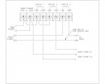
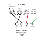
Today, I successfully wired my 2 speed Hayward 1Hp Superpump to the PE153 timer in Mode 2 according to the wiring diagram below. I would also like to run my Aquarite Swim pure plus so that it only comes on while the pump is on low. It is currently set to 120V source wiring and is currently powered with a long extension cord. Which terminals do I connect the 3 wires (white, black and ground) to? I have searched the forums and I can't find the answer to this specific question. Thanks in advance!

Alison
109507
 
  • Like
Reactions: Cyclist7531
You posted a 230V wiring diagram and you say your SWG is 120V. Those are not compatible.

Confirm your pump is 230V.

Can your SWG be changed to 230V?
 
Thanks for the reply.

Yes, the pump is 230V. The SWG can be changed to 230V, if so on what terminals would I make the connections so that it comes on only when the pump is on low?

Does this also mean that any auxiliary load that I put on circuit 3 would also have to be 230V?

Alison
 
Your swg needs to be changed to 230v. You should be able to set the on off times for aux the same as the low speed pump. Black would go to terminal one, White would go to terminal 8, a jumper from 5 to 7, and green to ground.

Edit: line terminals are not common, a source is needed at line terminals.
 
Last edited:
Hi Again.

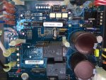
When I took off the cover from the aquarite to look at the circuit board, it doesn't have the screw connectors for the power supply numbered from 1 to 4 with the jumpers that can be moved. It is a corded model for the Canadian market that was probably 120V off the shelf. I did not remove the circuit board to see if there were jumpers somewhere behind, but I could feel behind the numbered connectors and there did not appear to be anything there.

For now, I will program the timer so that it stays on low speed most of the time, and leave the aquarite plugged into the extension cord.

Does anyone know if I have another option?

Thanks,

Alison

IMG_1219.JPG
 
Where is the P153 powered from? Is the source close to the timer?
What I really want to know, is there a way to get a neutral into the timer enclosure?

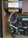
Also take a picture of the transformer in the Aqua-Rite.
 
Something like this should work: Waterproof timer. You can add 30 minutes to start and end of your pump timer to make up for possible timer sync issues. The flow sensor will prevent swg operation in case the two timers get completely out of sync.
 
Last edited:
Instead of using the timer, maybe use a current sensing relay on the low side line to turn on the relay to switch 120v to your SWCG. I use this current sensing device, CR4395-EH-120-110-X-CD-ELR-I. It senses current on one of the pump's 220v lines and switches 120V to my SWCG. Current trip point is adjustable. In your setup, run the low side line (red in your schematic) through the transformer loop
 
Thanks for the replies.

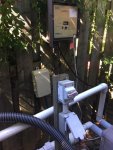
Here are the requested photos. I have two 240V outlets which were originally setup one for the single speed pump and one for the heater, with an on/off toggle switch. One of the outlets is now used to power the timer and the other is usually free (especially since the heater is not working right now). The heater would only be used when the pump was manually switched to high, and so the timer would be in override mode during its operation. An additional power line to the timer could be unplugged and replaced with the heater power cord when we want to use the heater.


IMG_1228.JPGIMG_1227.JPG
 

Enjoying this content?

Support TFP with a donation.

Give Support
They kinda hamstrung you with that power hookup. You're pretty much stuck with 120 volt.

It's not a normal setup, but you could set the timer up as Mode 4. Once you do that; in order to get the swg to run on low speed, switch low and high speed hookup. That way the 3rd circuit will run when the pump is running on low. Doing it that way you'll have to remember to program circuit 1 for the low speed times and circuit 2 for the high speed times.
 
Great. I just want to clarify what I think are the connections.

Instead of using a jumper to power circuit 3, I use an additional 240 line into to the timer. Do I connect just the green wire (neutral) to terminal 7 or use either of the new black or white wires as well? Do I terminate each of the unused wire(s) with a screw connector? The swg then gets connected across 7 and 8 and the ground wire to the ground lug in the timer enclosure.

I can then use mode 4 as suggested above if I switch the connections to the pump on 4 and 6, or continue to use mode 2, just making sure that the program for circuit 3 only comes on at the same time as circuit 2?

I just want to make sure I get this right, as I find the wiring diagrams a little confusing.

Thanks,
 
Thank you, thank you!

Finally a wiring diagram that I understand! Okay, based on this diagram, I have a new plan. I will disconnect the power cord from the swg and instead connect to the the timer, hot(black) going to 7, and the neutral as a pass through to the swg to terminal 1. Ground will be connected to timer ground lug. Then I will connect 8 to terminal 4 in swg, and ground wire to both the timer and the swg ground lugs.

I will use mode 4 and so switch the hi and lo wires in the timer.

The extension cord will then be connected to the timer instead of the swg. So I am not getting rid of the extension cord, but I won’t have to deal with disconnecting the swg when I run the heater. Does this make sense?

Thank you for your patience,

Alison
 
What you propose will work fine.

The hardest thing you'll have to keep straight is that circuit one is Low speed and circuit two is Hi speed. I'd suggest making a note about that and laminating it and having it somewhere near the timer. Even in the cover of the box would be a good idea, just in case someone else ever works on it.
 
Thank you, thank you!

Finally a wiring diagram that I understand! Okay, based on this diagram, I have a new plan. I will disconnect the power cord from the swg and instead connect to the the timer, hot(black) going to 7, and the neutral as a pass through to the swg to terminal 1. Ground will be connected to timer ground lug. Then I will connect 8 to terminal 4 in swg, and ground wire to both the timer and the swg ground lugs.

I will use mode 4 and so switch the hi and lo wires in the timer.

The extension cord will then be connected to the timer instead of the swg. So I am not getting rid of the extension cord, but I won’t have to deal with disconnecting the swg when I run the heater. Does this make sense?

Thank you for your patience,

Alison


Keep in mind that you will have to bring a neutral and hot to the box where the timer is unless there is already 120 volts there.
 
I'm not 100% sure, so don't do this, but, if you needed to wire the SWG for 230 volts I think that you could wire directly to the transformer.

You would remove the 4 colored wires from the upper left and connect the white and violet together and then connect grey to one leg of power and blue to the other power leg.

There are two sets of windings on the primary side of the transformer. Grey and violet go to one set and blue and white go to the other set.

Both windings take 120 volts. For 120 volt input, the windings are in parallel. Grey and white or blue are connected to one line and violet and unused white or blue are connected to the other line.

For 240 volts, the windings are put in series by connecting one wire from each winding together (grey with white or blue or violet with white or blue) and then power to the remaining two wires.

Note: Don't do this because I am not 100% sure that this would work.

You could also replace the circuit board if you needed to run on 230.

In any case, you should be able to get it working with the current plan.
 
Last edited:
Also, note that it looks like the box only takes a T5. If you look to the right of the 4 colored wires, you can see a jumper that allows you to select a T5 or T15. By jumping the two points, you should be able to switch to a T-15 when you need a new cell.
 
Thanks everyone for your replies.

I considered changing the main board, but at $288 cad from amazon I’ll wait until it actually needs replacing. It’s been going strong since 2008, with only replacing the cell once. When I need to replace the cell, I’ll look into changing to a t15.

I’m heading off to my parents with the kids for a week or so I’ll implement the plan when I get back. Hubby didn’t want me to mess with the timer right before I left in case he was left with a dead pump with no idea how to fix it!

Alison
 

Enjoying this content?

Support TFP with a donation.

Give Support
Thread Status
Hello , This thread has been inactive for over 60 days. New postings here are unlikely to be seen or responded to by other members. For better visibility, consider Starting A New Thread.