Wiring help for a CircuPool RJ60+

ultranothing

Member
Mar 26, 2020
8
06351
Pool Size
14500
Surface
Plaster
Chlorine
Salt Water Generator
SWG Type
CircuPool RJ-60
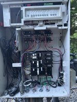
Hey there! We just got our cell and flow switch installed on our plumbing (scary!) and now we've got the control module mounted up and are trying to get it wired to power. We have a Jandy variable speed pump and want to ensure that the unit only runs when the pump is on (double failsafe). The problem is that we can't seem to get power to the unit. We use iAquaLink automation systems and the pump is controlled digitally. We traced the wires from the top of the box labeled "filter pump" and connected the wires to the load side of the relay that they lead to, but nothing happened. We checked the fuses and all the connections and even brought it inside and switched it over to 120v, attached a household plug and were able to get power to the unit to test that it's operational. We also hooked it up to "aux 2" which controls the blower and heater and were able to get power there. But it simply will not work when connected to the pump relay (and the pump is running!).

I've attached a few pictures. Thank you to the volunteers who help us with this stuff :D
 

Attachments

  • IMG_8050.jpg
    IMG_8050.jpg
    511.6 KB · Views: 11
  • IMG_8051.jpg
    IMG_8051.jpg
    602.5 KB · Views: 10
I wanted to also add that we did do some research here and came across this thread from a few years back which detailed pretty much our same situation. The relay which appears to be connected to our "pump filter" *also* has two devices connected to it. It's pretty much exactly as we have it (but of course must be missing some very key thing).
 
Welcome to TFP! :wave: If someone doesn't answer your question right away, I'm sure @Jimrahbe can help you with this one. Hang tight and enjoy the forum.
Thanks! Glad to have you guys as a resource here - especially when we're getting our hands dirty with this thing :D

Apparently I've been a member for five years and never posted...
 
Welcome to TFP.

Please show us how you connected the RJ60 power to the filter pump relay. I don't see it in the picture you posted.

The circled red relay is usually the filter pump relay.

The filter pump must be active to turn on the relay with the LED lit as circled in green.

1747529405997.png
 
  • Like
Reactions: ultranothing
Welcome to TFP.

Please show us how you connected the RJ60 power to the filter pump relay. I don't see it in the picture you posted.

The circled red relay is usually the filter pump relay.

The filter pump must be active to turn on the relay with the LED lit as circled in green.

View attachment 647119
Hi, thanks! I've attached a picture of how we've wired the SWG (we took the picture after disconnecting so it is not representing being hooked up). The wires from the "filter pump" appear to lead to the top middle relay and we've wired in the black wire from the RJ60 to "load 1" and the white wire to "load 2". These load points now each contain three wires. We're not sure what other devices or systems are connected to these, as when we traced the wires they appear to go out of the panel and into the ground.

The relay you've circled in red does not appear to have anything connected to it (the very top two screws). Is that still an active relay, even with no wires connected?
 

Attachments

  • How wires hook up.png
    How wires hook up.png
    719.7 KB · Views: 8
Last edited:
What model pump do you have?

Do you have a gas heater?

OK, they did not use the standard relay for the filter pump, but that is fine.

You should not put three wires under one screw. When you have three wires to connect you need to use a wire nut or 4-wire WAGO connector to connect the three wires to a pigtail and connect the pigtail to the LOAD screw,
 
It's a Jandy Pro series variable speed ePump. 2.7hp, I believe? We do have a gas heater.

So there would be no power to the unit with three wires fully secured and compressed inside the load screws, as is? Aren't pigtails and WAGO connectors just easier and more efficient ways to connect the wires, but essentially to the same thing(s), in this case? I'm happy to use those, but do you think the lack of them is causing the unit to not power on?

I did wonder why they decided to not use the standard relay for the filter pump, as it appeared in the diagram I saw.

Edit: I see now that it's unsafe if the relay isn't specifically rated. I will be sure to use a different, approved method of attaching the wires. But I still wonder if I should at least have power to the unit if that's where it's supposed to be hooked up, despite the poor method.
 
Last edited:
Your VS pump should get constant power and not be switched on the LOAD side of the relay.

I think the two wires are for your pump and heater.

The pump wires should be moved to the LINE side screw to be constantly powered. Then you have room to put the heater and SWG power under the LOAD screw.

You need to trace and confirm the existing wires to understand what you are doing.

I don’t know why your SWG did not get power before. I would have needed to see how it was connected.
 
I just did a RJ60 install on a jandy system on Friday but I have no pictures of the relay setup. Whichever relay you think is for the pump should have the load side power off and on with the press of the pump button while having the meter connected. If the pump is wired to the load side you'll need to move it to the line side which is constantly powered and then connect the RJ60 controller to the two load side contacts on the dame relay. MAKE SURE TO SWITCH THE CONTROLLER BACK TO 240 V BEFORE HOOKING IT UP TO THE RELAY.
 

Enjoying this content?

Support TFP with a donation.

Give Support
Your VS pump should get constant power and not be switched on the LOAD side of the relay.

I think the two wires are for your pump and heater.

The pump wires should be moved to the LINE side screw to be constantly powered. Then you have room to put the heater and SWG power under the LOAD screw.

You need to trace and confirm the existing wires to understand what you are doing.

I don’t know why your SWG did not get power before. I would have needed to see how it was connected.
Went out this morning and got some WAGO connectors. Tried wiring the SWG to the pump relay with pigtails - nothing. Changed the wires for the pump from the LOAD side to the LINE side and put the SWG on the LOAD side - nothing.

Took ALL the wires off the relay which leads from the filter pump connector wires - the pump still runs. Something, something "dummy relay"? From the research we've done.

I just don't get it, man.
 
Do you have a multimeter?

Check the voltage at the LOAD screws.

If there is voltage there and the SWG is not powered then follow the wires into the SWG and follow the voltage. Somewhere yiu have a basic wiring problem.
 
We used a multimeter to check some of the relays. We tested the load and line points on the relay that connects to "filter pump" and the line points were pushing power but the load points were not. We hooked up the SWG to the line points and the system turned on and appears to be working fine.

Apparently, we didn't notice that every time we'd hook up this SWG and flip the breaker, that the breaker we thought was for the UV system would trip. We didn't notice because the UV seems to have been tripping that breaker for a few years now, and I suppose we thought it was normal.

I dunno, the whole thing is a rat's nest of insanity and there's things hooked to things that have no power, and...whatever. It's hooked up to the line screws and says it's generating chlorine. I don't know if it's actually generating chlorine; cell volts says 25ish, the green "generating" light is on, etc., but I'm not seeing any action in the cell (even at MAX power) and we have about fifteen "return" jets in our pool with the in-floor cleaning system, etc., so any bubbles I might see are being distributed pretty broadly.
 
Last edited:
Another update: We went out and turned off the pump via iAquaLink because we wanted to see if the system, as wired, would also disable the SWG. When we disabled the pump, the SWG turned off - but due to no flow. When we turned the pump back on, the SWG would not restart and turned off completely. We then realized that it was tripping the breaker for what is labeled as "filter pump relay". We repeated this a few times and it happened each time. One time, it also tripped the surge protector.

So...for some reason, it worked fine with everything on for about five hours today, and after our little test, now it won't.

Failing pump? It is about six years old now. Six seasons of New England weather...