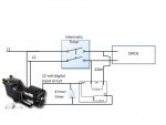
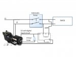
So, I know I posted this wiring diagram in another post. At the point in time it was just a concept. Now that I've implemented it I'd like to share my experience. I really like the way it works. Your mileage may vary!
What this setup allows me to do is control my salt water generator and pump using the same timer.....they can never get out of sync (the clock may not be correct if it loses power, but the SWCG will not run unless the pump is running....this is critical in my opinion). The current settings have the pump running about 8 1/2 hours a day and the SWCG set at 100% (so it runs 8 1/2 hours also).
If I decide I need more chlorine I simply add pump run time. If I just need more pump run time I can increase the pump run time and decrease the SWCG output percentage. If I need an extra blast of chlorine (like after a storm or party) I just throw the tripper on the intermatic and wala, more chlorine and pump time.
What I really like about this setup is I can bring on the pump anytime I want to with out the SWCG coming on. For instance, if I come home from lunch and want to do some testing. I set the timer for 60 minutes, do my test after 30, add my chemicals if needed and go back to work. The pump runs until the time expires and all is good in my world.


