Timer Choice

I hear you :)

First... based on advice here I looked in to the need for a fireman's switch, the heater is a Hayward and states it doesn't need one.

Now to the wiring, I pulled off the current switch, it has red, green and blue coming in. Green is ground/earth, red and blue go to the two hot terminals on the switch. Black wires come off the other poles of the switch and go off to the pump.

So... I'm pretty sure I have two 110v feeds that are joined up at the pump, i.e. I need to follow the diagram above that shows two 110v coming in to L and N, just need to determine how to run two loads from there, whether to just "pair them up" or not.
 
Looking at the diagrams in the instructions, NC1 and NC2 are not used for any application, including dual loads. I assume you will need to run both loads off N01 and N02, but not sure how to wire it. NC=Normally Closed and NO=Normally Open according to the instructions. Again, I'm not sure what that means.
 
/\ what Mike said.

I need to follow the diagram above that shows two 110v coming in to L and N, just need to determine how to run two loads from there, whether to just "pair them up" or not.
There isn't two 110v coming in to L and N. I don't have any experience with this device in particular. From what I can tell, the device can accommodate 120-277 VAC incoming AC to function.

For 110 VAC feed; connect the "N" to the white service neutral bus bar. Connect the hot black wire (L1) to "L" respectively.
For 220 VAC feed; connect the black (L1) to L and Red (L2) to N or vice-versa. They are interchangeable.

As for the COM1 and COM2, these are just 2 sets of "SPDT" DRY contacts as explained above by Mike. Similar to a light switch that you can turn on and off when called upon by the built-in controller. Depending on your application and load current demand, you might get away using the same source feeding terminals "L' or "N" as you can see in the diagram.

It is not necessary to use both COM1 and COM2 together to turn on/off a single device or equipment.

correction: I re-read Mike's previous posts and learned that COM1 and COM2 cannot be controlled independently (bummer). I am guessing, both sets of dry contact (COM1 and COM2) are controlled by a single "DPDT" relay. But where it is made from, I will not be surprised if both COM1 and COM2 shares the same SPDT relay. You'll never know what's up on their sleeves. Could use a multimeter!
 
Last edited:
I think the unit expects either 110 or 240 as a feed whereas here I have two 110 feeds that are combined to become my 220 supply, I think I have confirmed that from looking at how the current switch is wired.

I think we agree that NC1 and NC2 are not used - they are just for "normally closed" situations.

NO1 and NO2 are the two "hot outputs" - typically.

If I had a european style 240v supply I'd have three wires, live, neutral and ground so it'd be straightforward. Similarly if it was all 110v its straightforward. The peculiarity is these two 110v being combined to make by 220v input - the box doesn't seem to "naturally" like that - EXCEPT for the diagram Rancho posted earlier. The limitation I think is that diagram only shows (as it is) the ability to support a single device rather than two.

Now, if that single output could just be split to the two maybe I'm good to go?
 
I think the unit expects either 110 or 240 as a feed
Correct! This device accepts 120-277VAC. Auto detect or auto ranging, no need for a voltage selector switch.

whereas here I have two 110 feeds that are combined to become my 220 supply, I think I have confirmed that from looking at how the current switch is wired.
No offense but I am completely lost.

I think we agree that NC1 and NC2 are not used - they are just for "normally closed" situations.

NO1 and NO2 are the two "hot outputs" - typically.
Here's an illustration of a DPDT relay. Please try to visualize how the 2 set of dry contacts changeover when the coil is energized.


If I had a european style 240v supply I'd have three wires, live, neutral and ground so it'd be straightforward.
Brilliant, you got this! US standard, do not use Neutral but any combination of L1, L2 and L3.

Now, if that single output could just be split to the two maybe I'm good to go?
A multimeter is your best friend.
 
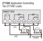
This is the diagram from the instructions for connecting two loads. Hopefully someone can provide direction based on the diagram.

View attachment 79745

I think this diagram illustrates the issue, this is a 277vac feed input to the switch and two similar outputs when the switch is activated.

The issue seems to be that in the US a "220v" supply is actually two 110v lines combined, hence why my switch has two inputs not one. Usually a switch (such as on a light) would have one wire, the live, which it breaks/makes, the neutral continues and is always connected.

So my 220v to my pump is made up by combining two 110v feeds, the switch isn't really geared up for this by default.
 
The picture in post 17 is key, it takes two 110v hot inputs and provides a matching pair of outputs, the problem is there's only one pair. I suspect I can run two outputs off NO1 and NO2 like this to get me the two feeds for the pump and the heater:

220.jpg
 
I am apprehensive to provide a definitive answer, but that's the way I would do it. Here are the load ratings for the Wion timer:

N.O. Contacts:
40A Resistive, 120~277VAC
1HP, 16A FLA, 96A LRA, 120VAC
2HP, 10A FLA, 60A LRA, 277VAC
30A Ballast, 120VAC
20A Ballast, 277VAC
15A Tungsten, 120VAC
30A Resistive, 28VDC

Not sure what it all means, but you want to make sure your connected components don't exceed max amp rating.

The connection shown in your switch would be similar to connections to an Intermatic timer; two lines in on terminals 1 and 3, and two loads piggybacked on terminals 2 and 4.

Sorry I can't be of more help.

BUMP for some expert input.

Mike.
 

Enjoying this content?

Support TFP with a donation.

Give Support
Chris,

We're here to help but I am not sure where the confusion is coming from. The T104R (steel box) has been around for many years but not sure about the WiOn 50054. The choice is yours!
The options to wire the WiOn are already posted in this thread for your reference. And as Mike mentioned, you can wire the WiOn the same way you would wire a T104R to meet your needs.

For 220V equipment, you need 2 phases and NO Neutral (Wht wire). It doesn't make a difference where you hook L1 phase (Blk) and L2 Phase (Red). If you break either or both phases, the equipment under load is OFF. Of course you need the green wire for Gnd and AWG#8 bare solid copper if the equipment calls for bonding (feel free to research on this).
In the below diagram I changed the wht to red. I assumed the Propane Heater is 220V and the filter pump is a 220V single speed. Now, do you think it make sense to you? Let us know if you have any concerns?

The following link is the typical installation and wiring diagram for the Intermatic T104, in case you decide to take this route!
http://www.inyopools.com/HowToPage/how_to_install_an_intermatic_t104_timer.aspx

http://waterheatertimer.org/How-to-wire-T104-Intermatic-timer.html

I appreciate all of the discussion and advice, it is very, very helpful. I agree we have settled on the most likely configuration, the only unknown is whether the Wion will be ok with two feeds of each hot output, I suspect it will be fine. If I was adding an electric heat pump I think it'd be a very different level of concern but from all that I have read I think all should be fine.

As I arrange to get the heater hooked up I'll verify whether I need to have a permit / electrician via the pool guys or whether I can DIY, I just wanted to be as informed as possible to avoid an electrical having to go off and research all of this on my nickel.

As you said I think we're good and I appreciate the discussion and advice.
 
From what I read, the WiOn is rated by the manufacturer at 40A resistive :scratch:. The conclusion is that often, contactors and relays can handle a higher amperage across the contacts when the load is resistive (Light / Heat) than when it is inductive (Motor / Motion).

Btw... please bear in mind, I am in no way encouraging you to DIY. You may want to call in an electrician if you're not confident working around with electricity.
That way, you can expand your knowledge while watching their back :study:... :cheers:
 
While I hate to change direction I'm feeling it may make sense to return the Wion and get an Intermatic as it's more of a known quantity at this stage for my application. While I like the whole home automation thing I'm not sure it is really necessary for me at this time.

Having said that I also suspect I may not run the heater constantly and need to consider that, it seems likely I'd use the heater occasionally, I'm inclined to put a timer on the pump but have the heater be manual for now. I think it should still be downstream of the pump so it cannot be on unless the pump is running but I want to be able to run the pump without the heater coming on. I'll talk to the pool guy about the best setup I guess as to whether the heater controls are sufficient for this or if I should add an intermediate switch.
 
That's not a bad idea. I use a pair of manual timers (low speed/high speed) to run my regular pump and the heater is manually operated. I may someday add a Pentair Easy Touch controller to the system, but I also know how quickly current technology ages which makes me apprehensive. I only use the WiOn switch control the pump for the waterfall/slide which is used only intermittently while were actually swimming. Having voice/phone control saves us trips back and forth to the pool shed to flip a manual switch. I still think for $60, the WiOn switch is a great cost-effective way to add automation to a basic system.

Good luck,

Mike.

Now I'm tempted to run both through an Intermatic and put the Wion between it and the heater... then I could run the pump on a timer and manually turn on the heat (only when the pump is running) from wherever.

If I had the pump run for say 6-8 hours every morning I could flip the heat on (with the Wion) on Friday night such that it would kick in with the next pump cycle.
 
Each time your pump timer turns off your Wion switch will lose power and connection to the network. You will have to rely on the Wion to reboot and reconnect each time it receives power. Not saying it won't do it, but seems like to much can go wrong. If you can wire your heater to the Wion with constant power you wouldn't have to rely on the continuous reboots. Just my 2 cents.

The Intermatic timer in your OP is not rated for outdoor use. The Intermatic 104R is probably a better choice, even inside of your equipment room.
 
The heater is still in its box on a pallet, I was going by some of the articles I have read. I think that in line with what you have I should return the Wion, get the Intermatic, wire as we have discussed and turn the heater on and off manually.

I think i was focusing in running the heat daily and assuming the heater could/would be configured to turn on whenever power was applied - ie whenever the pump ran.

I agree with with what you’re saying, both powered from the timer but the heater manually turned on and off at the panel.
 
Thread Status
Hello , This thread has been inactive for over 60 days. New postings here are unlikely to be seen or responded to by other members. For better visibility, consider Starting A New Thread.