The Arduino - Intex SWG

New2Me

0
LifeTime Supporter
Jun 2, 2008
322
SW Indiana
Intex - inexpensive SWG unit with limited control.
Arduino - an open-source electronics prototyping platform based on flexible, easy-to-use hardware and software. It's intended for artists, designers, hobbyists, and anyone interested in creating interactive objects or environments.

Yank out the "brain" of the Intex and insert an Arduino in its place. Now you have everything you need to build it the way you want it. I posted the program that I am using at - http://www.arduino.cc/cgi-bin/yabb2/YaBB.pl?num=1269366253
You are invited to look at it, play with it, laugh at it, and me, too, if you want!
You can modify it to do what ever you want to, as long as you can write the right code! It isn't hard to do, is fun to learn, and you can say that you did it yourself!
I really like the start delay, maybe one of the "big boys" will see that is a good idea, too!
 
what do you mean by "start delay"?

Having the delay just lets me use the one clock/timer, and know that if it drifts, it doesn't matter.

With the original controls, I had it set to come ON 1-2 hours after the pump did, but the drifting clocks would advance enough to have the unit come ON before the pump, and then it would err on "No Flow" and need to be reset, not generating any chlorine, even after the pump kicked ON. Any momentary blip in the power would also reset it.
I now have this plugged into an outlet that is powered along with the pump by a simple Intermatic timer. I have the pump set to come ON at 3 in the afternoon, and the SWG delay 3 hours. I get home from work after 5, so when I take a test sample, the water is "stirred" a little bit, and as long as I get it before 6, no chlorine has been added to my sample. Also the sun is off the pool by 6, so what the SWG is adding isn't losing to the sun.
I can also turn the pump ON to vacuum, (or for any other reason) for up to 3 hours (more if you cycle it) with out adding chlorine.

Having it remember what it is programmed to run is what I really wanted, and a self correcting flow error.
I scrapped the salinity test circuitry, so it won't err on LOW or HIGH salt either, but there are still fuses for current limiting. The green LED is powered across the cell, so if a fuse blows it won't be ON. I keep track of additions that I make to the pool, so I can be fairly accurate calc'ing the salinity on paper, and it seems that most of the posted salt errors people have aren't caused by salt level, but by some other factor.

I started trying to modify my program to use a % control, but gave up because I am NOT a programmer, and keeping track of the cell ON time, and reverse time was stumping me, and because I was satisfied with what I have ( the KISS principle.) I am thinking of changing the cell reversal time to only change polarity every-other run (or longer,) as I don't have much calcium build-up and am aware that cell life is longer with out the reversals (the owners manual said that it reversed every 20 hours, but I doubt that it could remember that long.)
I also thought about adding a LCD to replace the seven-segment LED displays. That would allow displaying much more info, like volts, amps, etc.., (and would actually simplify the program code,) but would require modifying the packaging.

If anyone wants to pick up the ball and run with it, I'd be happy to share what little I know about it!
 
I modified my program to only reverse polarity (self-clean) every x runs, instead of doing it 1/2 through every run. It's posted on the Arduino forum. Now with it set to run 4 hours/day and self clean every 5 run cycles it will be 20 hours between cleanings, which is what Intex says it does stock.

I'm still messing around with a counting program that will track actual operation time and time between cleanings, to get to a % power control, but I still get myself lost in the if..else forest.

I've also discussed putting in another relay that would control the power to the pump, and shut it off if the flow sensor doesn't detect flow within a set start time.

Always welcome any discussions or help. How do you think an Intex Electronic Chloorine Generator (IECG) should operate?
 
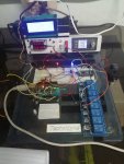
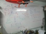
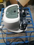
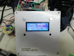
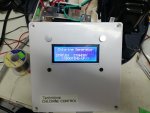
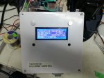
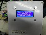
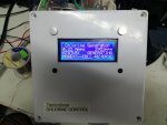
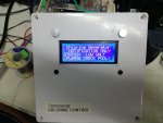
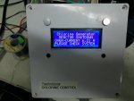
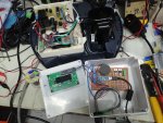
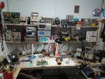
This thread has been very inspirational. So I got myself a cheap unit from ebay, yanked out the electronics, did some design work on the whiteboard and wrote some code for the Arduino. Got it running on the bench finally andIMG_20200211_092323.jpg will have it on the pool next week. Will post pics etc as they become available.IMG_20200210_223743.jpgIMG_20200211_093358.jpg
 
/*
ARDUINO MODIFIED INTEX - Chlorine Generator Control System
Cletus Berkeley 2020/03/07 12:30PM
Ver. 08.01 Locked-Down: 05:15PM

NOTE: This version assumes ONLY the salinity cell is energized (left hand cell). The right hand cell MUST remain totally de-energized
*/
//TIMING AND CONSTANTS SETUP

int Startup=5000UL; // Startup delay - this allows time for pump to start circulation

int Restart=5000; // Low-Flow restart delay - this allows time for flow stabilization

int SalConst=1059; // Consant for converting Amperes to Salinity (SalConst= Tested PPM/Display Amps)


int OverSALT=7.5; // Higher than this value stop generating "HIGH SALT" (Amperes)
int UnderSALT=2000; // Lower than this value stop generating "LOW SALT" (Req'd PPM - 20%)


const long revTime=21600000L; //Interval to reverse electrodes (6-HOURS) 60*60*1000*6

//const long revTime=60000; //FOR TESTING PURPOSES - to reverse electrodes (60-seconds)


// # # # # # # # # # # # # # # # # # # # # # # # # # # # # # # # # # # # # # # # # # # # #


//Input and Output pin configuration
int FLOWsensor=11;
int FWDPolarity=5;
int REVPolarity=12;
int BUZZ=10;
int mainRelay=9; // Conrols power to electrodes / Soft-start


// LCD DISPLAY LIBRARY
#include <SoftwareSerial.h>
#include <Wire.h>
#include <LCD.h>
#include <LiquidCrystal_I2C.h>
#define I2C_ADDR 0x27 // Define I2C Address where the SainSmart LCD is
#define BACKLIGHT_PIN 3
//LiquidCrystal_I2C lcd(I2C_ADDR,En_pin,Rw_pin,Rs_pin,D4_pin,D5_pin,D6_pin,D7_pin);
LiquidCrystal_I2C lcd(I2C_ADDR,2,1,0,4,5,6,7);


// Variables that will change:

int fwdState = LOW; //to set the Normal Polarity
int revState = LOW; //to set the Reverse Polarity
// Generally, you should use "unsigned long" for variables that hold time
// The value will quickly become too large for an int to store
unsigned long previousMillis = 0; // will store last time cycle time was updated

// constants that won't change:
const long interval = revTime; // interval at which to reverse (milliseconds)

void setup() {
Serial.begin(9600); //a debugging aid

digitalWrite(11, HIGH); //Initialize the flow-sensor pin to high


// configure the digital pins as inputs and outputs:
pinMode (FLOWsensor, INPUT);
pinMode(FWDPolarity, OUTPUT);
pinMode(REVPolarity, OUTPUT);
pinMode (BUZZ, OUTPUT);
pinMode (mainRelay, OUTPUT);

digitalWrite(mainRelay, LOW); //Initialize the main relay to off
digitalWrite(BUZZ, LOW); //Initialize piezo buzzer to off

// Configure the LCD DISPLAY
lcd.begin (20, 4); // Switch on the backlight
lcd.setBacklightPin(3,POSITIVE);
lcd.setBacklight(HIGH);
lcd.home();

// System Initialization and Welcome Screen
lcd.clear();
lcd.setCursor ( 0, 0 );
lcd.print(" CLETUS BERKELEY");
lcd.setCursor ( 0, 1 );
lcd.print(" Ver.: 8.01");
lcd.setCursor ( 0, 2 );
lcd.print(" Chlorine Generator");
lcd.setCursor ( 0, 3 );
lcd.print("Ver. H5.00 Mar 2020");
delay (2000);
lcd.clear();
lcd.setCursor ( 0, 0 );
lcd.print(" Chlorine Generator");
lcd.setCursor ( 0, 2 );
lcd.print("STATUS: PLEASE WAIT");
lcd.setCursor ( 0, 3 );
lcd.print(" <<INITIALIZING>>");
delay (Startup); // Startup delay - this allows time for pump to start circulation
}

void loop() {
digitalWrite(BUZZ, LOW); //if buzzer was on turn it off


// HERE WE READ THE ACS715 CURRENT SENSOR DATA

unsigned int x=0;
float AcsValue=0.0,Samples=0.0,AvgAcs=0.0,AcsValueF=0.0,SalinityPPM=0.0;

for (int x = 0; x < 150; x++){ //Acquire 150 samples
AcsValue = analogRead(A0); //Read current sensor values
Samples = Samples + AcsValue; //Add samples together
delay (10); // Time between samples 10ms
}
AvgAcs=Samples/150.0; //Take Average of Samples

//((AvgAcs * (5.0 / 1024.0)) converitng the read voltage in 0-5 volts
//2.5 is offset(assuming arduino is working on 5v so the viout at no current comes
//out to be 2.5 which is the offset. If Arduino is working on different voltage
//the offset must be altered according to the input voltage)
//0.066v(66mV) is rise in output voltage when 1A current flows at input (66mV per Amp)

AcsValueF = (2.5 - (AvgAcs * (5.0 / 1024.0)) )/0.066;

SalinityPPM = (AcsValueF * SalConst); // Here we try to corelate amps to Salinity PPM using a simple conversion value

Serial.print(" Amperes ");
Serial.println(AcsValueF);//Print the read current on Serial monitor (debugging)
Serial.println(" ");
Serial.print(" PPM Salinity ");
Serial.println(SalinityPPM);//Print the read Salinity on Serial monitor (debugging)
Serial.println(" ");


// %%%%%%%%%%%%%%%%%%%%%%%%%%%%%%%%%%%%%%%%%%%%%%%%%%%%%%%%%%%%%%%%%%%%%%%%%%%%%%%%%%%%%%%
// HERE WE READ THE ACS715 VOLTAGE SENSOR DATA

unsigned int y=0;
float VcsValue=0.0,VSamples=0.0,AvgVcs=0.0,VcsValueF=0.0;

for (int y = 0; y < 150; y++){ //Acquire 150 samples
VcsValue = analogRead(A2); //Read Voltage sensor values
VSamples = VSamples + VcsValue; //Add samples together
delay (10); // Time between samples 10ms
}
AvgVcs=VSamples/150.0; //Take Average of Voltage Samples

//((AvgVcs * (5.0 / 1024.0)) converitng the read voltage in 0-5 volts
//2.5 is offset(assuming arduino is working on 5v so the viout at no current comes
//out to be 2.5 which is the offset. If Arduino is working on different voltage
//the offset must be altered according to the input voltage)
//0.066v(66mV) is rise in output voltage when 1A current flows at input (66mV per Amp)

VcsValueF = AvgVcs*30/1023; // Tweak the AvgVcs multiplier to calibrate voltage
Serial.print(" Volts ");
Serial.println(VcsValueF);//Print the read voltage on Serial monitor (debugging)
Serial.println(" ");
Serial.println("- - - - - - - - - - - - - - ");
Serial.println(" ");

// <><><><><><><><><><><><><><><><><><><><><><><><><><><><><><><><><><><><><><><><><><>

// LOW SALT CURRENT MONITOR

if (SalinityPPM < UnderSALT)
{
lcd.clear();
lcd.setCursor ( 0, 0 );
lcd.print(" Chlorine Generator");
lcd.setCursor ( 0, 1 );
lcd.print(" NOTIFICATION ONLY ");
lcd.setCursor ( 0, 2 );
lcd.print("STATUS: LOW SALT");
lcd.setCursor ( 0, 4 );
lcd.print("<PLEASE CHECK POOL>");
digitalWrite (BUZZ, HIGH); // Audible Alarm
delay (2000);
}
else {
}

//HIGH CURRENT TRIP (was initially setup for High Salt, but HIGH CURRENT is more appropriate)
if (AcsValueF > OverSALT)
{
lcd.clear();
lcd.setCursor ( 0, 0 );
lcd.print(" Chlorine Generator");
lcd.setCursor ( 0, 1 );
lcd.print(" REACTOR SHUTDOWN");
lcd.setCursor ( 0, 2 );
lcd.print("OVER-CURRENT");
lcd.setCursor ( 13, 2 );
lcd.print(AcsValueF);
lcd.setCursor ( 18, 2 );
lcd.print("A");

lcd.setCursor ( 0, 4 );
lcd.print("PLEASE CHECK SYSTEM");
digitalWrite (mainRelay, LOW);
digitalWrite (BUZZ, HIGH); // Audible Alarm
delay (60000);
}
else {
}


// WATER FLOW VERIFICATION AND DISPLAY UPDATE
if (digitalRead(FLOWsensor) == HIGH){
digitalWrite (mainRelay, LOW); // Flow Sensor is open - No water is flowing
delay(1000);
lcd.clear();
lcd.setCursor ( 0, 0 );
lcd.print(" Chlorine Generator");
lcd.setCursor ( 0, 1 );
lcd.print(" WARNING");
lcd.setCursor ( 0, 2 );
lcd.print("STATUS: LOW FLOW");
lcd.setCursor ( 0, 4 );
lcd.print(" REACTOR STOPPED");
}
else {

// THIS IS THE NORMAL DISPLAY UPDATE PROTOCOL
if (fwdState == LOW) {
lcd.clear();
lcd.print(" Chlorine Generator");
lcd.setCursor ( 0, 2 );
lcd.print("STATUS: GENERATING");
lcd.setCursor (0, 1 );
lcd.print(AcsValueF);
lcd.setCursor (4, 1 );
lcd.print("A V");
lcd.setCursor (6, 1 );
lcd.print(VcsValueF,1);
lcd.setCursor (13, 1 );
lcd.print(SalinityPPM);
lcd.setCursor (17, 1 );
lcd.print("ppm");
lcd.setCursor ( 0, 4 );
lcd.print("MODE: --NORMAL--->>>");

}
else {
// THIS IS THE CELL REVERSE DISPLAY UPDATE PROTOCOL
lcd.clear();
lcd.print(" Chlorine Generator");
lcd.setCursor ( 0, 2 );
lcd.print("STATUS: GENERATING");
lcd.setCursor (0, 1 );
lcd.print(AcsValueF);
lcd.setCursor (4, 1 );
lcd.print("A Sal:");
lcd.setCursor (13, 1 );
lcd.print(SalinityPPM);
lcd.setCursor (17, 1 );
lcd.print("ppm");
lcd.setCursor ( 0, 4 );
lcd.print("MODE:<--CELL-REVERSE");
}

delay(Restart); //Delay on restart of generator - time for flow to resume and stabilize
digitalWrite (mainRelay, HIGH);// Flow Sensor is closed - Water-flow established

}

// + + + + + + + + + + + + + + + + + + + + + + + + + + + + + + + + + + + + + + + + + + + + + +

// check to ascertain if it's time to Cycle the Electrodes; that is, if the difference
// between the current time and last time the electrodes cycled is greater than
// the interval at which the electrodes should be cycled.

unsigned long currentMillis = millis();


if (currentMillis - previousMillis >= revTime) {

previousMillis = currentMillis; //save the last time the the polarity relay cycled

// if the Polarity Relay is off turn it on and vice-versa (toggle):
if (fwdState == LOW) {
fwdState = HIGH;
} else {
fwdState = LOW;
}

// if the Polarity Relay is off turn it on and vice-versa (toggle):
if (fwdState == LOW) {

}

// if the Polarity Relay is off turn it on and vice-versa (toggle):
if (fwdState == LOW) {
revState = HIGH;
} else {
revState = LOW;
}

// set the relay with the fwdState of the variable:
digitalWrite(FWDPolarity, fwdState);


}

}
 
Last edited:

Enjoying this content?

Support TFP with a donation.

Give Support
/*
INTEX Chlorine Generator Control System
Cletus Berkeley 2020/02/11 08:20AM
Ver. 04.30 Locked-Down: 03:45PM

*/
//TIMING AND CONSTANTS SETUP

int Startup=5000UL; // Startup delay - this allows time for pump to start circulation

int Restart=5000; // Low-Flow restart delay - this allows time for flow stabilization

int SalConst=700; // Constant for converting Amperes to Salinity (SalConst= Tested PPM/Display Amps)


int OverSALT=3600; // Higher than this value amps stop generating "HIGH SALT" (Req'd PPM + 20%)
int UnderSALT=2400; // Lower than this value amps stop generating "LOW SALT" (Req'd PPM - 20%)


//const long revTime=21600000L; //Interval to reverse electrodes (6-HOURS) 60*60*1000*6

const long revTime=60000; //FOR TESTING PURPOSES - to reverse electrodes (60-seconds)


// # # # # # # # # # # # # # # # # # # # # # # # # # # # # # # # # # # # # # # # # # # # #


//Input and Output pin configuration
int FLOWsensor=11;
int FWDPolarity=5;
int REVPolarity=12;
int BUZZ=10;
int mainRelay=9; // Conrols power to electrodes / Soft-start


// LCD DISPLAY LIBRARY
#include <SoftwareSerial.h>
#include <Wire.h>
#include <LCD.h>
#include <LiquidCrystal_I2C.h>
#define I2C_ADDR 0x27 // Define I2C Address where the SainSmart LCD is
#define BACKLIGHT_PIN 3
//LiquidCrystal_I2C lcd(I2C_ADDR,En_pin,Rw_pin,Rs_pin,D4_pin,D5_pin,D6_pin,D7_pin);
LiquidCrystal_I2C lcd(I2C_ADDR,2,1,0,4,5,6,7);


// Variables will change:

int fwdState = LOW; // used to set the Polarity
int revState = LOW; // State used to set the Polarity
// Generally, you should use "unsigned long" for variables that hold time
// The value will quickly become too large for an int to store
unsigned long previousMillis = 0; // will store last time cycle time was updated

// constants won't change:
const long interval = revTime; // interval at which to reverse (milliseconds)

void setup() {
digitalWrite(11, HIGH);
Serial.begin(9600);

// configure the digital pins as inputs and outputs:
pinMode (FLOWsensor, INPUT);
pinMode(FWDPolarity, OUTPUT);
pinMode(REVPolarity, OUTPUT);
pinMode (BUZZ, OUTPUT);
pinMode (mainRelay, OUTPUT);

digitalWrite(mainRelay, LOW); //Initialize the main relay to off
digitalWrite(BUZZ, LOW); //Initialize buzzer to off

// Configure the LCD DISPLAY
lcd.begin (20, 4); // Switch on the backlight
lcd.setBacklightPin(3,POSITIVE);
lcd.setBacklight(HIGH);
lcd.home();

// System Initialization and Welcome Screen
lcd.clear();
lcd.setCursor ( 0, 0 );
lcd.print(" CLETUS BERKELEY");
lcd.setCursor ( 0, 1 );
lcd.print(" Ver.: 4.30");
lcd.setCursor ( 0, 2 );
lcd.print(" Chlorine Generator");
lcd.setCursor ( 0, 3 );
lcd.print(" Ver. 4.24 Feb 2020");
delay (2000);
lcd.clear();
lcd.setCursor ( 0, 0 );
lcd.print(" Chlorine Generator");
lcd.setCursor ( 0, 2 );
lcd.print("STATUS: STANDBY");
lcd.setCursor ( 0, 3 );
lcd.print(" <<BOOTING-UP>>");
delay (Startup); // Startup delay - this allows time for pump to start circulation
}

void loop() {
digitalWrite(BUZZ, LOW); //if buzzer was on turn it off

// HERE WE READ THE ACS715 CURRENT SENSOR DATA

unsigned int x=0;
float AcsValue=0.0,Samples=0.0,AvgAcs=0.0,AcsValueF=0.0,SalinityPPM=0.0;

for (int x = 0; x < 150; x++){ //Get 150 samples
AcsValue = analogRead(A0); //Read current sensor values
Samples = Samples + AcsValue; //Add samples together
//delay (3); // let ADC settle before next sample 3ms
}
AvgAcs=Samples/150.0; //Take Average of Samples

//((AvgAcs * (5.0 / 1024.0)) converitng the read voltage in 0-5 volts
//2.5 is offset(assuming arduino is working on 5v so the viout at no current comes
//out to be 2.5 which is the offset. If Arduino is working on different voltage
//the offset must be altered according to the input voltage)
//0.066v(66mV) is rise in output voltage when 1A current flows at input (66mV per Amp)

AcsValueF = (2.5 - (AvgAcs * (5.0 / 1024.0)) )/0.066;
SalinityPPM = (AcsValueF * SalConst); // Here we try to corelate amps to Salinity PPM using a simple conversion value
Serial.print(AcsValueF);//Print the read current on Serial monitor
delay(50);


// %%%%%%%%%%%%%%%%%%%%%%%%%%%%%%%%%%%%%%%%%%%%%%%%%%%%%%%%%%%%


// HIGH/LOW CURRENT MONITOR / REACTOR TRIP
//LOW SALT
if (SalinityPPM < UnderSALT)
{
lcd.clear();
lcd.setCursor ( 0, 0 );
lcd.print(" Chlorine Generator");
lcd.setCursor ( 0, 1 );
lcd.print(" NOTIFICATION ONLY ");
lcd.setCursor ( 0, 2 );
lcd.print("STATUS: LOW SALT");
lcd.setCursor ( 0, 4 );
lcd.print("<PLEASE CHECK POOL>");
digitalWrite (BUZZ, HIGH); // Audible Alarm
delay (2000);
}
else {
}


//HIGH SALT
if (SalinityPPM > OverSALT)
{
lcd.clear();
lcd.setCursor ( 0, 0 );
lcd.print(" Chlorine Generator");
lcd.setCursor ( 0, 1 );
lcd.print(" REACTOR SHUTDOWN");
lcd.setCursor ( 0, 2 );
lcd.print("OVER-CURRENT");
lcd.setCursor ( 13, 2 );
lcd.print(AcsValueF);
lcd.setCursor ( 18, 2 );
lcd.print("A");

lcd.setCursor ( 0, 4 );
lcd.print("PLEASE CHECK SYSTEM");
digitalWrite (mainRelay, LOW);
digitalWrite (BUZZ, HIGH); // Audible Alarm
delay (60000);
}
else {
}


// FLOW-SENSOR TEST AND DISPLAY UPDATE
if (digitalRead(FLOWsensor) == HIGH){
digitalWrite (mainRelay, LOW); // Flow Sensor is open - No water is flowing
delay(1000);
lcd.clear();
lcd.setCursor ( 0, 0 );
lcd.print(" Chlorine Generator");
lcd.setCursor ( 0, 1 );
lcd.print(" WARNING");
lcd.setCursor ( 0, 2 );
lcd.print("STATUS: LOW FLOW");
lcd.setCursor ( 0, 4 );
lcd.print(" REACTOR STOPPED");
}
else {

// THIS IS THE DISPLAY UPDATE PROTOCOL (FWD)
if (fwdState == LOW) {
lcd.clear();
lcd.print(" Chlorine Generator");
lcd.setCursor ( 0, 2 );
lcd.print("STATUS: GENERATING");
lcd.setCursor (0, 1 );
lcd.print(AcsValueF);
lcd.setCursor (5, 1 );
lcd.print("Amps");
lcd.setCursor (13, 1 );
lcd.print(SalinityPPM);
lcd.setCursor (17, 1 );
lcd.print("ppm");
lcd.setCursor ( 0, 4 );
lcd.print("MODE: --NORMAL--->>>");

}
else {
// THIS IS THE DISPLAY UPDATE PROTOCOL (REV)
lcd.clear();
lcd.print(" Chlorine Generator");
lcd.setCursor ( 0, 2 );
lcd.print("STATUS: GENERATING");
lcd.setCursor (0, 1 );
lcd.print(AcsValueF);
lcd.setCursor (5, 1 );
lcd.print("Amps");
lcd.setCursor (13, 1 );
lcd.print(SalinityPPM);
lcd.setCursor (17, 1 );
lcd.print("ppm");
lcd.setCursor ( 0, 4 );
lcd.print("MODE:<--CELL-REVERSE");
}

delay(Restart); //Delay on restart of generator - time for flow to resume and stabilize
digitalWrite (mainRelay, HIGH);// Flow Sensor is closed - Water-flow established

}

// + + + + + + + + + + + + + + + + + + + + + + + + + + + + + + + + + + + + + + + + + + + + + +

// check to see if it's time to Cycle the Electrodes; that is, if the difference
// between the current time and last time the electrodes cycled is greater than
// the interval at which the electrodes should be cycled.

unsigned long currentMillis = millis();

if (currentMillis - previousMillis >= revTime) {
// save the last time you blinked the LED
previousMillis = currentMillis;

// if the LED is off turn it on and vice-versa:
if (fwdState == LOW) {
fwdState = HIGH;
} else {
fwdState = LOW;
}

// if the Relay is off turn it on and vice-versa:
if (fwdState == LOW) {

}

// if the Relay is off turn it on and vice-versa:
if (fwdState == LOW) {
revState = HIGH;
} else {
revState = LOW;
}

// set the LED with the ledState of the variable:
digitalWrite(FWDPolarity, fwdState);

}

}
A couple of hints from a guy what has been writing code for 40 years...

When using braces {}, and you write the statement, do the closing brace, with a copy of the statement as a comment for example

} // if (x == y)

Now add the code to be executed between, you will be thankful when you get more then 4 layers deep, of knowing what statement belong to which brace. Makes it harder to forget one as well.
Anything that appears in multiple places, consider turning into a function, so you can simply call the function.
Hey, thanks for the tip!
 

Enjoying this content?

Support TFP with a donation.

Give Support
Thread Status
Hello , This thread has been inactive for over 60 days. New postings here are unlikely to be seen or responded to by other members. For better visibility, consider Starting A New Thread.