Tapping to Aquarite

Jul 2, 2017
7
Montreal
Hi Folks,

I see threads talking about tapping to Jandy PDA here and here
And I was wondering if it is possible to tap into Hayward / Goldline Aquarite unit.
I understand that this is not an automation unit, however if it is possible to at least remotely read the data that can be displayed on the unit.
Things like
  • Water temperature
  • Salt Level
  • Error Codes
    • No Flow
    • Check Salt
    • High Salt
    • Inspect Cell
  • Current
  • Desired Output %
  • ...

And at best to remotely control and change the settings

I see that there is an LED for *Remotely Controlled*
So this should be theoretically possible

Has anyone managed to figured out how to tap to it?

Ideally it would be DIY project, however if there are readily available commercial packages (obviously the cheaper the better) I'm interested to know.

Can any knowledge gathered from the above threads be used to reverse engineer this unit?

Thanks in advance.
 
Read this post - Aquarite and Aqualink working together

Apparently you can do this with this: Chlorinator Translator

I think I misread this it looks like you are just looking for homegrown automation.

Thanks @PoolGate

Although my preference is DIY, I don't mind purchasing a device if it is decently priced,
Unless I'm misunderstanding, looking at Chlorinator Translator docs, it's an interface between Aqualink PDA and Aquarite.
I do not have AquaLink PDA, otherwise I would have followed the OP referenced threads.

Thanks
 
I have the Hayward Aqua Connect connected to my Pro Logic system. According to the Aqua Connect documentation, it works with Pro Logic and Aqua Rite Pro.

Tha Aqua Connect allows me to do anything I can do at the Pro Logic panel remotely on my phone. It's a bit slow since you are going through the Hayward webserver which is communicating with the Aqua Connect at your home. But, it has worked well for me. There have 2 instances when I wanted to use it, but Hayward's webserver was down.

And...it ain't cheap! Best price I found was on Amazon.
 
Thanks @PoolGate

Although my preference is DIY, I don't mind purchasing a device if it is decently priced,
Unless I'm misunderstanding, looking at Chlorinator Translator docs, it's an interface between Aqualink PDA and Aquarite.
I do not have AquaLink PDA, otherwise I would have followed the OP referenced threads.

Thanks

badabing -

I think you might have miss read something about the Chlorinator Translator. I believe it works with Aqualink RS and PDA systems. Also it works with the Rev T, T1, and T2 with the iAqualink. So, if you haven't found a solution, you might want to revisit it and even contact them with your setup to verify that it will work.
 
Hi Folks,

I see threads talking about tapping to Jandy PDA here and here
And I was wondering if it is possible to tap into Hayward / Goldline Aquarite unit.
I understand that this is not an automation unit, however if it is possible to at least remotely read the data that can be displayed on the unit.
Things like
  • Water temperature
  • Salt Level
  • Error Codes
    • No Flow
    • Check Salt
    • High Salt
    • Inspect Cell
  • Current
  • Desired Output %
  • ...

And at best to remotely control and change the settings

I see that there is an LED for *Remotely Controlled*
So this should be theoretically possible

Has anyone managed to figured out how to tap to it?

Ideally it would be DIY project, however if there are readily available commercial packages (obviously the cheaper the better) I'm interested to know.

Can any knowledge gathered from the above threads be used to reverse engineer this unit?

Thanks in advance.

badabing -

To answer this inquiry, yes, since the Aquarite was supported by the earlier Aqualink RS systems, you can see and control the SWG. The issue is if the SWG is already connected to an Aqualink system, all you can do is listen to the data packets going back and forth. If it isn't and you want to control it, you will have to be the master since the Aqualink is the master when it is connected. As for what information you can get, all that the SWG supplies is salt level and error codes. It doesn't report water temperature, current or desired output %. When you use the communication link, the desired output is controlled by the comm link and the knob on the panel has no effect. You indicate that you are looking to do a DYI project. This DYI, does it to replace the Aqualink or to control the Aqualink?
 
Thanks @dflynn60
My SWG is only connected to aquarite, I don't have Aqualink system.
You say that if it isn't I have to be the master, how can I be the master?
I'd be interested in getting any information possible even if it is only the salt level and Error Codes, specially the error codes could be useful as I don't have to go under the patio where aquarite is to know / see if there are any error codes.

If you have any information on how to achieve that, I'd be greatly appreciative,
Thanks

BB

FYI - SWG stands for Salt Water Generator. The AquaRite is a SWG.

So, what do you have connected to the AquaRite's communications connector? If you look at the manual for the AquaRite, there is a 4 pin connector on the board. This normally gets connected to the AquaLink or other pool control system. This 4 wire connection uses what is called RS485 interface. It is a differential interface and only one device can be driving the 2 wires. BTW - the other 2 wires are power and ground. In a Aqualink configuration, the AquaLink supplies 10V to any device that is connected to it. You will need to do the same for the AquaRite if you plan to communicate with it.

Now from a protocol stand point, the AquaLink is the Master of the RS485 bus. All other devices are slaves. In the protocol that AquaLink uses, everyone has an address. The Aqualink is the master and has an address of 00 hex. The AquaRite has an address of 50 hex. So when the Aqualink whats to tell something and get status from the AquaRite, the AquaLink sends a data packet of information addressed to the AquaRite. Once all of the bytes of the data packet is sent, the AquaLink then listens for a data packet back to it's self. The AquaRite sees the data packet and then will respond to the data packet with the proper response. Since I have a Aqualink and AquaRite, I have listen to the data packets and have reverse engineered them. Here is the basic data packet that you will need to send to the AquaRite. All values are in hex represented by 0x.

0x10 0x02 0x50 0x11 Percent Checksum 0x10 0x03 The Percent is the percentage of chlorine you want generated. If the value of 101 is sent the AquaRite is in BOOST mode. The Checksum is the sum of all the bytes up to but not including the Checksum byte.

If the data packet is excepted by the AquaRite, it will respond with following data packet.

0x10 0x02 0x00 0x12 PPM STATUS Checksum 0x10 0x03 The PPM is the PPM of your salt level. I will leave up you to decode through testing. The STATUS, I will leave up you to decode through testing.

One more thing on the data packet. If you notice, the 0x10 with another byte afterward indicate the start and ending of the data packet. If a byte in the middle of the data packet is 0x10, it will be followed by 0x00. The receiving device will drop the 0x00 to form the data packet to be evaluated.

Hope this helps.
 

Enjoying this content?

Support TFP with a donation.

Give Support
FYI - SWG stands for Salt Water Generator. The AquaRite is a SWG.

So, what do you have connected to the AquaRite's communications connector? If you look at the manual for the AquaRite, there is a 4 pin connector on the board. This normally gets connected to the AquaLink or other pool control system. This 4 wire connection uses what is called RS485 interface. It is a differential interface and only one device can be driving the 2 wires. BTW - the other 2 wires are power and ground. In a Aqualink configuration, the AquaLink supplies 10V to any device that is connected to it. You will need to do the same for the AquaRite if you plan to communicate with it.

Now from a protocol stand point, the AquaLink is the Master of the RS485 bus. All other devices are slaves. In the protocol that AquaLink uses, everyone has an address. The Aqualink is the master and has an address of 00 hex. The AquaRite has an address of 50 hex. So when the Aqualink whats to tell something and get status from the AquaRite, the AquaLink sends a data packet of information addressed to the AquaRite. Once all of the bytes of the data packet is sent, the AquaLink then listens for a data packet back to it's self. The AquaRite sees the data packet and then will respond to the data packet with the proper response. Since I have a Aqualink and AquaRite, I have listen to the data packets and have reverse engineered them. Here is the basic data packet that you will need to send to the AquaRite. All values are in hex represented by 0x.

0x10 0x02 0x50 0x11 Percent Checksum 0x10 0x03 The Percent is the percentage of chlorine you want generated. If the value of 101 is sent the AquaRite is in BOOST mode. The Checksum is the sum of all the bytes up to but not including the Checksum byte.

If the data packet is excepted by the AquaRite, it will respond with following data packet.

0x10 0x02 0x00 0x12 PPM STATUS Checksum 0x10 0x03 The PPM is the PPM of your salt level. I will leave up you to decode through testing. The STATUS, I will leave up you to decode through testing.

One more thing on the data packet. If you notice, the 0x10 with another byte afterward indicate the start and ending of the data packet. If a byte in the middle of the data packet is 0x10, it will be followed by 0x00. The receiving device will drop the 0x00 to form the data packet to be evaluated.

Hope this helps.

Awesome, and many thanks dflynn60
Sorry for the delayed response, I was on holidays.

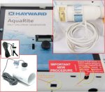
To answer your question, All I have connected to Aquarite 4 wire connector is the flow control
See attached pic


I doubt that the flow control is providing 10v to aquarite, I assume in this configuration aquarite is acting as the master.
Would that be a correct assumption
I'm not sure if the flow control is just acting as flow control or also as temperature sensor, as aquarite displays the temperature.

Do you think if I get one of these
Amazon.com: Gearmo Pro 5ft USB to RS485-RS422 FTDI Chip - Windows 10 supported USB to Serial Adapter: Computers Accessories
Connect just the data lines to the 4 pin connector along with the flow sensor, I would see the communication on my PC in a serial terminal?

With aqualink, I assume the flow control connects to aqualink? would that be correct assumption?
How does aqualink send the data about the flow? have you decoded that? or you just decoded the cell percent command?
What is sending the temperature? the CELL or the flow sensor?

Lastly, is it possible to get status from aquarite about any error codes?
I guess once everything is figured out, I can use ESP8266 based controller and code something up.

Thanks
BB
 

Attachments

  • aquarite.jpg
    aquarite.jpg
    58.3 KB · Views: 44
Awesome, and many thanks dflynn60
Sorry for the delayed response, I was on holidays.

To answer your question, All I have connected to Aquarite 4 wire connector is the flow control
See attached pic


I doubt that the flow control is providing 10v to aquarite, I assume in this configuration aquarite is acting as the master.
Would that be a correct assumption
I'm not sure if the flow control is just acting as flow control or also as temperature sensor, as aquarite displays the temperature.

Do you think if I get one of these
Amazon.com: Gearmo Pro 5ft USB to RS485-RS422 FTDI Chip - Windows 10 supported USB to Serial Adapter: Computers Accessories
Connect just the data lines to the 4 pin connector along with the flow sensor, I would see the communication on my PC in a serial terminal?

With aqualink, I assume the flow control connects to aqualink? would that be correct assumption?
How does aqualink send the data about the flow? have you decoded that? or you just decoded the cell percent command?
What is sending the temperature? the CELL or the flow sensor?

Lastly, is it possible to get status from aquarite about any error codes?
I guess once everything is figured out, I can use ESP8266 based controller and code something up.

Thanks
BB

I think you are a little confused. The RJ connector on the bottom of the case (flow control) is just an input from a switch that tells the AquaRite that there is water flow in the pipe. If there is no water flow, the AquaRite doesn't turn on the cell. This connector is not the RS485 communications connection. Please look at the manual for the AquaRite. Here is a link to one. https://hayward-pool-assets.com/assets/documents/pools/pdf/manuals/AquaRite-AQR-Owner.pdf?fromCDN=true

On page 13, it references the the 4 pin communications connector. It is inside the box, behind the panel. You will need to remove the panel to see it. If you don't have any electrical high voltage knowledge, then I strongly don't recommend you removing the panel until you find someone to help you. Behind the panel is high voltage that will KILL YOU!

Back to page 13, you will see connection assignment in one of the figures. It shows +15V but you can use +10V to +15V on that pin. The device you are looking at buying doesn't supply and I wouldn't expect it too power. You will need to supply that voltage. BTW it is DC voltage, not AC. In a AquaLink setup, this voltage is supplied by the AquaLink.

As for the Master/Slave, the AquaRite is never the master, only the slave.

I do look forward on hearing our success.

dflynn60
 
I think you are a little confused. The RJ connector on the bottom of the case (flow control) is just an input from a switch that tells the AquaRite that there is water flow in the pipe. If there is no water flow, the AquaRite doesn't turn on the cell. This connector is not the RS485 communications connection. Please look at the manual for the AquaRite. Here is a link to one. https://hayward-pool-assets.com/ass...f/manuals/AquaRite-AQR-Owner.pdf?fromCDN=true

On page 13, it references the the 4 pin communications connector. It is inside the box, behind the panel. You will need to remove the panel to see it. If you don't have any electrical high voltage knowledge, then I strongly don't recommend you removing the panel until you find someone to help you. Behind the panel is high voltage that will KILL YOU!

Back to page 13, you will see connection assignment in one of the figures. It shows +15V but you can use +10V to +15V on that pin. The device you are looking at buying doesn't supply and I wouldn't expect it too power. You will need to supply that voltage. BTW it is DC voltage, not AC. In a AquaLink setup, this voltage is supplied by the AquaLink.

As for the Master/Slave, the AquaRite is never the master, only the slave.

I do look forward on hearing our success.

dflynn60

dflynn60

Thank you very much, this is very valuable information
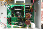
As the manual is not clear about the exact location of the connector, I searched online for images and found this.
I'm assuming that it is the connector on the right side which I drew a red box around.
Can you confirm?
1548096991050.png

As for the voltage of +10V, should I connect the ground of the 10V dc to the ground of RS-485 ?
I'll be reading up and preparing for spring when I finally get a chance to access my Aquarite
By any chance is the protocol modbus? or proprietary?

Many Thanks
BB
 
dflynn60

Thank you very much, this is very valuable information
As the manual is not clear about the exact location of the connector, I searched online for images and found this.
I'm assuming that it is the connector on the right side which I drew a red box around.
Can you confirm?
View attachment 92229

As for the voltage of +10V, should I connect the ground of the 10V dc to the ground of RS-485 ?
I'll be reading up and preparing for spring when I finally get a chance to access my Aquarite
By any chance is the protocol modbus? or proprietary?

Many Thanks
BB

BB -

Yes the red box in your picture is the RS485 interface connector. As for the ground, the ground on the connector is the ground reference for both the RS485 and the ground for the 10V. So, yes connect the 10V ground to the RS485 ground. DO NOT connect this ground to earth ground in the box.
To answer your last question, the protocol is not Modbus from what I can tell. It is proprietary but there is information out there on what it is. In my Dec 29 response, I gave you information on what it is.

dflynn60
 
Thread Status
Hello , This thread has been inactive for over 60 days. New postings here are unlikely to be seen or responded to by other members. For better visibility, consider Starting A New Thread.