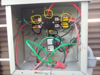
This is my new salt cell current sensing switch set up. I am posting this for any opinions/advice people want to give on the set up. It is working well but what should I have done differently? Also, while many threads talk about doing this there was not a clear diagram so I hope this helps. The numbers/colors refer to the drawing on the picture.
The best options for a SWG current sensing switch seem to be a current sensing relay but those are around $90. My goal was less expensive option. I used a current sensing switch, a 240vac contactor, and a metal electrical enclosure.
*****I am not saying this will work for you or even be safe for your set up. Be safe hire a professional and I am not one. I welcome advice. ********
Everything I have is wired 240vac including salt cell and pump.
Green numbers are parts:
Green 1 – Contactor 2-pole 240, volt coil (I bought a 40 amp because it was cheaper than 30 amp either should work). I used this one which was $11.49 at the time I bought it
https://www.amazon.com/gp/product/B08H8X41P6
Green 2 - Normally Open Current Sensing Switch Adjustable AC. I used the following on which was $8.99 when I bought it. There are many switches of the same type on amazon. This is adjustable so I can have it switch on at a pump speed of 1200rpm but off at only a display load on the pump.
Amazon.com: Heayzoki Normally Open Current Sensing Switch Adjustable AC 0.2-30A SZC23-NO-AL-CH,Current Sensing Relay Switch,Self-Powered, No External Power Supply Required. : Industrial & Scientific
Green 3 – Fuse holder might not be needed as everything is in the box.
Green 4 – 240V LED status light (not needed)
You will also need other parts such as an appropriately labeled electrical enclosure, wires, connectors, electrical housing, etc.
Red circles and numbers are as follows:
Red 1 – Line in
Red 2 – Line out to salt cell
Red 3 – Pump line in
Red 4 – pump line out
Line in from supply (red 1):
Red in from supply (red 1) to supply side of contactor at Yellow 1.
Black in from supply (red 1) to supply side of contactor at Black 1.
Green in from supply to ground in box and ground out to load
Wires coming off of supply side of contactor (yellow 1 and black 1):
Red at yellow 1 to contactor coil at yellow 2.
Black at black 1 through inline fuse (green 3) to switch on load sensing switch (green 2) at connection black 3.
Wires coming off load sensing switch (black 3):
Black at switch (black 3) to contactor coil at black 2
Out to salt cell load:
Red on out load side of contactor (yellow 3) to salt cell (red 2)
Black on out load side of contactor (Black 4) to salt cell (red 2)
Green from ground nut to salt cell (red 2)
Pool pump wiring:
Solid wires that are not cut/uninsulated in box red/green/black from in (red 3) to out to pump load (red 4). Only one wire (red) through hole in load sensing switch.