Any Spa Techs in the house?
First a little background: I'm a long time TFP member on the pool side, but just now getting back into the Spa world after 20 years without one. I am also a hardcore DIY'er type (see my pool repaint thread) so when my wife found a "Free Hot Tub! Just take it away! Doesn't work!" Facebook marketplace ad on New Years day, we ran over and grabbed it.
The shell itself is in fantastic condition for it's age (2001 Marquis Mirage) and it holds water fine with no leaks. A quck look and I could see that the whole thing was mis-wired, sensors in the wrong places, etc, so I pulled the pack to check it all out. The pump tested out good (2-speed, 48 frame), the ozone generation was shot (looked original), so I pitched it, and this model had no blower. Easy peasy right? It was already wired for 110v, so I hooked it all back up according to the lid schematic, ran a temporary extension cord, and it came to life! Both topside panels worked, and the pump cycled both speeds. Everything looked great so I ran to Home depot, where I bought a Spa Panel and all the required stuff for a legit 220v hookup. I got it all wired up, moved the amperage jumper on the board from 20a-50a, GFCI tested good and I was cooking with juice! I tested and adjusted the pressure switch and it called for heat with a light on the panel, so I left it to warm up overnight. The next morning, it was still 50 degrees. Ugh! The heater coil ohmed out good, so I pulled the circuit board for further bench inspection, which brings me to the issue I have today.
The board is a Balboa 52149 "LEZURR1D". From the board layout it looks like a very common 2000's era design, and the mother of today's "LITE LEADER" boards which although newer, appear to have pretty much the same layout. I've done plenty of circuit board repairs on other devices, so I tested all the relays and found that the coil on the heater relay was shot and wouldn't activate when hit with bench voltage (this is the relay in the upper left corner when looking at the board as installed). Aha! I ordered a three-pack of relays (just in case), and a few days later replaced it. Back in the tub, everything was great! The relay engaged as it should and she heated right up to the default 100. Everything seemed great. The problem we soon realized, is that after doing all of the above, the pump wont cycle to high speed. When you press the pump button on either panel, it just cycles from OFF-->LOW-->OFF. It is supposed to be, and WAS working as a three state cycle: OFF-->LOW-->HIGH-->OFF. What gives? It isn't like it tries to go high and the relay doesn't work, it doesn't even try. I can swap the HI-LOW pump hot wires and it kicks right into high speed, so it's isn't the pump itself, the relay simply isn't being engaged by the board logic. It's as if the board is in a 1-speed pump mode. The thing is, there aren't any jumpers, etc in which to change pump behavior and it doesn't have a battery so cutting the power resets the board to the factory defaults. The only other thing that changed was the heater jumper, so I put it back on 20amp as a test to see if that made a difference, and it did not.
So I'm stumped! Any ideas or clues?
Thanks!
B.
First a little background: I'm a long time TFP member on the pool side, but just now getting back into the Spa world after 20 years without one. I am also a hardcore DIY'er type (see my pool repaint thread) so when my wife found a "Free Hot Tub! Just take it away! Doesn't work!" Facebook marketplace ad on New Years day, we ran over and grabbed it.
The shell itself is in fantastic condition for it's age (2001 Marquis Mirage) and it holds water fine with no leaks. A quck look and I could see that the whole thing was mis-wired, sensors in the wrong places, etc, so I pulled the pack to check it all out. The pump tested out good (2-speed, 48 frame), the ozone generation was shot (looked original), so I pitched it, and this model had no blower. Easy peasy right? It was already wired for 110v, so I hooked it all back up according to the lid schematic, ran a temporary extension cord, and it came to life! Both topside panels worked, and the pump cycled both speeds. Everything looked great so I ran to Home depot, where I bought a Spa Panel and all the required stuff for a legit 220v hookup. I got it all wired up, moved the amperage jumper on the board from 20a-50a, GFCI tested good and I was cooking with juice! I tested and adjusted the pressure switch and it called for heat with a light on the panel, so I left it to warm up overnight. The next morning, it was still 50 degrees. Ugh! The heater coil ohmed out good, so I pulled the circuit board for further bench inspection, which brings me to the issue I have today.
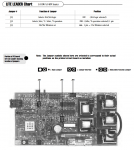
The board is a Balboa 52149 "LEZURR1D". From the board layout it looks like a very common 2000's era design, and the mother of today's "LITE LEADER" boards which although newer, appear to have pretty much the same layout. I've done plenty of circuit board repairs on other devices, so I tested all the relays and found that the coil on the heater relay was shot and wouldn't activate when hit with bench voltage (this is the relay in the upper left corner when looking at the board as installed). Aha! I ordered a three-pack of relays (just in case), and a few days later replaced it. Back in the tub, everything was great! The relay engaged as it should and she heated right up to the default 100. Everything seemed great. The problem we soon realized, is that after doing all of the above, the pump wont cycle to high speed. When you press the pump button on either panel, it just cycles from OFF-->LOW-->OFF. It is supposed to be, and WAS working as a three state cycle: OFF-->LOW-->HIGH-->OFF. What gives? It isn't like it tries to go high and the relay doesn't work, it doesn't even try. I can swap the HI-LOW pump hot wires and it kicks right into high speed, so it's isn't the pump itself, the relay simply isn't being engaged by the board logic. It's as if the board is in a 1-speed pump mode. The thing is, there aren't any jumpers, etc in which to change pump behavior and it doesn't have a battery so cutting the power resets the board to the factory defaults. The only other thing that changed was the heater jumper, so I put it back on 20amp as a test to see if that made a difference, and it did not.
So I'm stumped! Any ideas or clues?
Thanks!
B.
Last edited:
")