Re-Plumb salt water generator

I still don't understand why the SWG is connected directly to the pump and how scheduling is achieved. Will the connection to the pump send 230 volts to the RJ+ control center and only receive power when the VS pump is activated?
 
I still don't understand why the SWG is connected directly to the pump and how scheduling is achieved. Will the connection to the pump send 230 volts to the RJ+ control center and only receive power when the VS pump is activated?
yes I believe that is exactly how it is set up currently, the pump turns on and 2-3mins later the control center is powered, when the pump is off i have no power to the control center. Should it be set up a different way? Now may be the time to make any changes
 
  • Like
Reactions: Rancho Cost-a-Lotta
yes I believe that is exactly how it is set up currently, the pump turns on and 2-3mins later the control center is powered, when the pump is off i have no power to the control center. Should it be set up a different way? Now may be the time to make any changes
That's exactly the way it should be set up. I didn't know the Jandy pump had that capability. That makes the connection easier. You do not want the SWG powered on when the pump is off and there is no flow.
 
That's exactly the way it should be set up. I didn't know the Jandy pump had that capability. That makes the connection easier. You do not want the SWG powered on when the pump is off and there is no flow.
okay great so now the question is connect old wiring directly to CircuPool Control module or Junction box below to make my splice. I can handle that, Thank you guys so much!
 
Lots of great tips so far. Basing this on some of those and the biggest question is how much room you have in your horizontal.
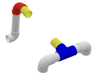
Based on your original photo, with the yellow in my diagram being your existing salt cell and pipe, how much room do you have? If you are at roughly 20, you should be okay.
1747844445418.png

You'll want to cut the yellow near the blue diverter, but leave enough room for your Tee fitting (the flow sensor that came with the RJ.). 2 inches should be minimum.
You'll want to cut the yellow near the red elbow, but leave enough room for your union - including sliding the rotating ring back. I'd say about 2.5 inches.
1747844660231.png


Then you can plug in your RJ. as such....
1747847137731.png

If you don't think you have enough room, you can put the flow switch before (below) the red elbow.
 

Attachments

  • 1747844751656.png
    1747844751656.png
    36.1 KB · Views: 1
Lots of great tips so far. Basing this on some of those and the biggest question is how much room you have in your horizontal.
Based on your original photo, with the yellow in my diagram being your existing salt cell and pipe, how much room do you have? If you are at roughly 20, you should be okay.
View attachment 648163

You'll want to cut the yellow near the blue diverter, but leave enough room for your Tee fitting (the flow sensor that came with the RJ.). 2 inches should be minimum.
You'll want to cut the yellow near the red elbow, but leave enough room for your union - including sliding the rotating ring back. I'd say about 2.5 inches.
View attachment 648168


Then you can plug in your RJ. as such....
View attachment 648173

If you don't think you have enough room, you can put the flow switch before (below) the red elbow.
That is an amazing illustration I really appreciate it, this will help my brain lol. thank you!
 
Make sure you install the flow switch after the SWG on the horizontal...

From the CircuPool RJ Manual:
When positioning the Flow Switch, there must be at least 6 to 12” (30cm) of straight pipe before the Flow Switch. If installed after the Electrolytic Cell, the Cell can be counted as straight pipe.
 

Enjoying this content?

Support TFP with a donation.

Give Support