Raypak 406A Gas Heater - clock/fireman switch

edima302

Well-known member
Jun 13, 2017
48
Marlboro New Jersey
Pool Size
22000
Surface
Plaster
Chlorine
Salt Water Generator
SWG Type
Pentair Intellichlor IC-40
[h=2][/h]
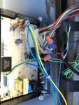
Need help with my Raypak gas heater. It is not lighting and am getting a clock/fireman switch message on the front panel. The pool and equipment are controlled by a Aqualink RS control panel and the heater doesn’t work in Auto or when I switch it to Service Mode. Anyone know what the issue can be ? I opened up the control panel and examined the wiring and all looks in tact but really don’t know what i'm looking at or if I have a firemans switch? I also opened up the Raypak front panel and the wires look ok. Not sure tho if the pilot is lit ? By the way, my spa side controller went bad so I disconnected that from the aqualinlk panel but even when I plug it back in the heater still does not fire up. thanks!​
 
Most likely the issue is a bad system board. I see a few of these a year. This unit does not have a pilot but it is an electronic spark type of light up.

Just to double check, if it is in REMOTE mode, take it out of that and see if the unit will light. I doubt it though.
 
Even on manual mode (the heater that is), I still can’t get it to light.. when you say a bad board do you mean the heater or the aqualink unit that controls everything ?
 
OK then it is the board. It is behind the display panel on the heater. So take the front door off, then there are 4 screws that hold the panel in place where the board is.
 
If the control was connected to the fireman's switch and it's open, you will get the error.

Check the fireman's switch and install a jumper to see if that works.

On millivolt heaters the fireman’s switch connection is a wire nut located in the Violet/Black wiring
between the manual toggle switch and the gas valve.


For AFT heaters the fireman’s switch connection is located on the 14-pin header connected to the digital
control board. Splice into the red wire jumper tagged
“Where necessary add “Fireman’s” switch circuit here”
to connect the time clock.
 
If the control was connected to the fireman's switch and it's open, you will get the error.

Check the fireman's switch and install a jumper to see if that works.

The fireman's switch/clock is already wired in the harness. If you use them, you cut the loop and connect the wires with wire nuts.
 
One thing to keep in mind, if the unit says "REMOTE" on the display , that means that they are using the wires for the remote option. That is the only way to control the heater from a automation system. I also do not believe the Aqualink RS system would work with this heater using the fireman/clock option. It should be a simple two wire to the heaters remote wiring harness.
 
It's probably not connected to the fireman's switch but I just wanted to check to be sure.

The message says that the loop is open.

Maybe something happened. It's worth a look before replacing the board.
 

Enjoying this content?

Support TFP with a donation.

Give Support
Hi JamesW.. good point I’ll post some pics later in hopes that we can narrow down the root cause.. one think to note since replacing the board is on the table is that I noticed that the display on the panel is
faded and some of the letters are half and not fully displaying.. read somewhere that that could be sun/heat related ?

- - - Updated - - -

And if I had to replace the board, is this something I can do myself ? Any idea where I can get a replacement? Amazon ?!
 
The board should be part number 013464F.

Just Google the number for replacement options. I think that it's something you should be able to do.

The main thing we need to know is if the fireman's loop is intact or not. If it is, then you probably need a new board.

How old is the heater?

This video shows how the remote is supposed to be wired.

Raypak 2-Wire Remote Setup for Gas Fired Heater - YouTube
 
  • Like
Reactions: Soupy
I didn’t get a chance to upload any pics last night as it’s been raining here in the east coast for what seems like weeks ! I hope to get a chance to later though
 
Sorry for the delay guys. Here are some pics. I don’t know what I’m looking at so hope someone does ..not sure if there is a fireman switch connected or what the 2 loose wires are
 

Attachments

  • 47AB8369-3222-4162-A3E7-B86EBA06A6B1.jpg
    47AB8369-3222-4162-A3E7-B86EBA06A6B1.jpg
    65.9 KB · Views: 77
  • 53B512E7-165C-421E-8CB5-F85B051A8E79.jpg
    53B512E7-165C-421E-8CB5-F85B051A8E79.jpg
    66 KB · Views: 68
Ok, they did use the Fireman's switch loop for the remote. Turn off power and then take apart the two wire nuts and then remove the remote wiring and connect the two red wires that are labeled Fireman's loop.

As noted on the label, it says not to put the remote there. The remote goes where the other label says remote, which is how the video shows the remote connection.
 
First, turn off the power.

The remote wiring is the black cable that has the red and black wires that go into the wire nuts.

The fireman's loop is the two red wires from the board that go into the wire nuts.

Remove the wire nuts, disconnect the red and black remote wires, cap them with wire nuts and move them out of the way.

Then connect the two red wires from the board together with one of the wire nuts.
 
JamesW you are a genius !! That worked and my heater is now working. One think I noticed tho is that it fired up and starting heating the pool on its own without me turning it on. That happened in auto and service mode. I have it heating the hot tub as we speak. What do you think it is ? I connected the 2 red wires from the board and put some electric tape individually around the red and black wires from the remote. Should I have connected the two together ?
 
Ok, we are pretty sure that the red and black wires go to the automation in the aqualink rs box. They should connect to Green 10-pin Terminal Bar terminals 1 and 2.

You should verify that. Once you verify that they go to the remote heater control, you can connect the wires to the remote wires.

Then, turn on remote. The remote control in the aqualink is just a switch that closes when the aqualink tells the heater to turn on.

The aqualink should have its own temperature sensor that you set to allow the aqualink to control the heater.

The fireman's loop should never have been cut. You just restored it back to how it came from the factory.

Right now the heater is running on its own controller. To use the remote control, you connect the remote wiring as shown in the video.

The 3 remote wires are blue, black with an orange stripe and orange with a black stripe. They have a tag that says "Where necessary, add pool/spa remote switch here".

The red and black wires should connect to the remote wires. One will connect to the blue wire and the other will connect to the black wire that has an orange stripe. The orange wire with a black stripe should be capped off.

There might be a problem with the remote wiring or switch in the aqualink because the original problem wouldn't have happened if the switch was closing. You should verify that the remote switch is good by checking the red and black remote wires for continuity when the aqualink is calling for heat.

Was the pump running when the heater turned on?

Have you always set the heater temperature in automation or on the heater?

Does the automation show the correct temperature?
 

Enjoying this content?

Support TFP with a donation.

Give Support
Thread Status
Hello , This thread has been inactive for over 60 days. New postings here are unlikely to be seen or responded to by other members. For better visibility, consider Starting A New Thread.