- Oct 1, 2022
- 812
- Pool Size
- 20000
- Surface
- Plaster
- Chlorine
- Salt Water Generator
- SWG Type
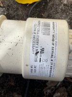
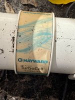
- Hayward Aqua Rite (T-15)
Hi my name is bill and I am a newbee
I have a Hayward Aqua Pro Logic system
The other day my pool person told me there was "no flow" and the cell was dead.
So I replaced the flow switch successfully and now there is flow
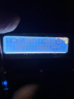
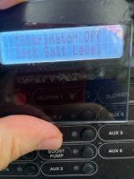
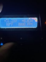
The cell seems dead as it says low salt 0000ppm and also the pool temp reads "ERR"
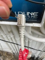
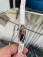
The cord to the cell appears nicked as someone closed the controller door on it.
I am wondering if this is a cord issue or cell issue.
I was reading pinout information on this forum and I see there are salt sensing and pool temp sensing wires in that cord
My plan is (if this makes sense) is to bare the area of the cord that is nicked and inspect continuity and splice if needed.
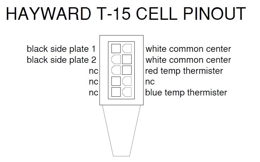
I know the connector has 10 pins but only 6 are used but I am not sure exactly which is pin 1 or pin 2 is it on the left or right ?
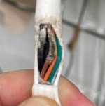
Addendum: Looking closely at the nick in the wire: I peeled the coating back and only the red wire is crushed.
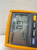
When I place my multimeter on the exposed wire and the other lead on the plug itself it looks like it has direct continuity to Pin 5 ie 3rd one down on left. The resistance between 6 and 10 is 9.6K ( 3rd and 5th down on right holding the plug that the cord is down and facing the connectors)
Shouldnt the red go to pin 6 ie not pin 5
Below is information from this site
"Holding the plug vertically with the cord going down and looking at the connection points. 1 is top left, 2 is top right, 3 is second down left and so on with 9 being lower left and 10 being lower right.[48]
I have a Hayward Aqua Pro Logic system
The other day my pool person told me there was "no flow" and the cell was dead.
So I replaced the flow switch successfully and now there is flow
The cell seems dead as it says low salt 0000ppm and also the pool temp reads "ERR"
The cord to the cell appears nicked as someone closed the controller door on it.
I am wondering if this is a cord issue or cell issue.
I was reading pinout information on this forum and I see there are salt sensing and pool temp sensing wires in that cord
My plan is (if this makes sense) is to bare the area of the cord that is nicked and inspect continuity and splice if needed.
I know the connector has 10 pins but only 6 are used but I am not sure exactly which is pin 1 or pin 2 is it on the left or right ?
Addendum: Looking closely at the nick in the wire: I peeled the coating back and only the red wire is crushed.
When I place my multimeter on the exposed wire and the other lead on the plug itself it looks like it has direct continuity to Pin 5 ie 3rd one down on left. The resistance between 6 and 10 is 9.6K ( 3rd and 5th down on right holding the plug that the cord is down and facing the connectors)
Shouldnt the red go to pin 6 ie not pin 5
Below is information from this site
"Holding the plug vertically with the cord going down and looking at the connection points. 1 is top left, 2 is top right, 3 is second down left and so on with 9 being lower left and 10 being lower right.[48]
- 1) Black - Power to cell
- 2) White - Power to cell
- 3) Black - Power to cell
- 4) White - Power to cell
- 5) Brown - Not used
- 6) Red - Goes to thermistor
- 7) Orange - Not used
- 8) Yellow - Not used
- 9) Green - Not used
- 10) Blue - Goes to thermistor.
Last edited: