Pentair Intelliflo VS Over Current Error

delyles

Member
Apr 23, 2020
22
Houston Texas
I am having a similar issue to ones I have seen posted.

Pentair Intelliflo VS pump hitting Over Current error. It appears to hit this error when the pump tries to ramp up quickly to scheduled higher speed at startup after priming. I am able to slowly ramp the RPMs up in Service mode and the pump will continue to run without hitting error until I get around 3000 RPMs, then the error is tripped. It does not trip the error at the same RPM level, sporadic based on how fast increase the RPM increments. I checked voltage at L1 and L2, it stays steady between 245-249 volts during operations and when the error is hit.

Anyone know of other things to check to determine if I have a bad Motor vs bad Drive?
 
How much power does it report at an RPM slightly below where it shuts off?

Is the motor noisy? Could be bearings or a restriction of the impeller. I would separate the motor from the wet end and inspect the impeller and diffuser for any restrictions.
 
I will observe that your 245-249 volts is on the high side of nominal voltage. Usually the voltage is between 220-240 volts with some voltage drop to the pump.

Do you have a solar PV system or battery system giving you different voltage then the electric utility?

@Ahultin @Mdragger88 thoughts on that voltage level?
 
Last edited:
How much power does it report at an RPM slightly below where it shuts off?

Is the motor noisy? Could be bearings or a restriction of the impeller. I would separate the motor from the wet end and inspect the impeller and diffuser for any restrictions.
Thanks, I actually had a new seal kit coming from Amazon today so I broke it open and replaced the seals. It was making some slight noises before but now runs smooth....but, when it initially started in Auto mode, it kicked on and ran fine at 3000 RPM, when I switched it to Spa mode it errored again with the over current error.

I shifted over to Service mode and ran it though the same low RPM to higher RPM process but it keeps erroring out. I did Disable the priming function and it now will let me manually get the RPMs to 3000 but errors when I try to go much higher.

The volts at L1 and L2 stay fairly consistent between 245 and 249. The screen shows wattage which it appears to be around 1900 Watts when it errors out.
 
I will observe that your 245-249 volts is on the high side of nominal voltage. Usually the voltage is between 220-240 volts with some voltage drop to the pump.

Do you have a solar PV system or battery system giving you different voltage then the electric utility?

@Ahultin @Mdragger88 thoughts on that voltage level?
No Solar or battery system, just electric power. Could the breaker in my subpanel be causing the issue? When I had the multi meter connected to L1 and L2 it stayed consistent between 245 -249.
 
No Solar or battery system, just electric power. Could the breaker in my subpanel be causing the issue? When I had the multi meter connected to L1 and L2 it stayed consistent between 245 -249.
A bad breaker might cause you to lose voltage but it would not cause high voltage.
 
I will observe that your 245-249 volts is on the high side of nominal voltage. Usually the voltage is between 220-240 volts with some voltage drop to the pump.

Do you have a solar PV system or battery system giving you different voltage then the electric utility?

@Ahultin @Mdragger88 thoughts on that voltage level?
Called up... not sure if I should be honored or scared 🤣
That voltage should not pose an issue. Ours routinely tests @246v with no load and looking at service standards for our provider (sdge) shows service standards of 220v-250v. My pump circuit at no load is currently 246v, with the pump running it drops to 239v

Looking back there are previous posts with similiar issues, all pointing to the drive as a result of a surge (which crazy enough looks to cost almost as much as a new pump). Have you had any surges (lightning strike etc) lately?
 
Our power company (PG&E) considers voltage to be within range from 228v to 252v (240v +- 5%). Although at the higher end of the range, I don't think that should be an issue. NEMA ratings are +- 10%.


Also, the Intelliflo has an overvoltage alarm so it should be able to detect any issue with that.

If you are sure the impeller spins freely without any restriction then the problem is most likely the drive.
 
The drive might be monitoring the three phase current going to the motor from the drive in addition to the single phase current going to the drive from the supply.

You should check the voltage, current and frequency going from the drive to the motor to see if the current on each of the three legs is equal and what the current is.

You will probably need to get a jumper to take the drive off of the motor to get access to the wires.

1679325096912.png


1679325228719.png

1679325344303.png

 
Last edited:

Enjoying this content?

Support TFP with a donation.

Give Support
Check the resistance of the motor windings by checking
L1 to L2
L1 to L3
L2 to L3

Make a jumper and check the voltage, current and frequency of the power going from the drive to the motor.

Check for continuity from each leg to ground to see if you have a ground fault.

A GFCI might not trip if you have a short to ground at the drive output to the motor since the drive isolates the incoming power from the outgoing power like a light transformer.
 
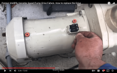
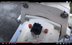
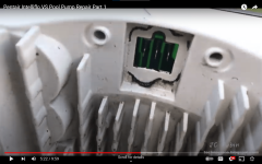
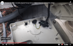
It looks like there are 3 power connections and 2 data connections from the drive to the motor.

The data connections might be for motor temperature, so you will probably have to make a jumper for the data as well.

Check the resistance of the data leads going to the motor.

It's likely to be a 10K thermistor that measures temperature.

So, you will be looking for about 10K ohms at about 77 degrees Fahrenheit (25 degrees C).

It looks like standard 1/4" spade connections, so you will probably be able to use 5 wires to jump from the drive to the motor with a female 1/4" spade on 1 side and a male 1/4" spade on the other side.

Note: Only do what you know you can do safely.

1679327432065.png
 
Check the input amperage.

If it is less than 16 amps, then the overcurrent alarm is likely to be due to an imbalance in the current going from the drive to the motor with one leg of three getting excessive amperage.

There might be a problem with the drive or the motor.

You can get a motor or drive, but you need to know which is bad.

In many cases, getting individual parts is almost always not a better choice than just replacing the whole pump.

1679328998616.png
 
The volts at L1 and L2 stay fairly consistent between 245 and 249. The screen shows wattage which it appears to be around 1900 Watts when it errors out.
1900 watts at 245 volts is 7.75 amps, which is not too high.

Check the input single phase amperage to see if it matches this calculation.

Most likely, the overcurrent is being measured at the three phase power going from the drive to the motor.

This is likely due to a voltage imbalance coming from the drive or a defect in one of the windings in the motor.

A resistance check should identify a bad winding.

A continuity check from each winding to the ground should identify a ground fault.
 
Thread Status
Hello , This thread has been inactive for over 60 days. New postings here are unlikely to be seen or responded to by other members. For better visibility, consider Starting A New Thread.