
Pentair Easy Touch Panel 3 amp relays tried to reset them
- Thread starter MahD
- Start date
You are using an out of date browser. It may not display this or other websites correctly.
You should upgrade or use an alternative browser.
You should upgrade or use an alternative browser.
what's it drawing for current?
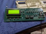
the two rows of blocks on the LCD (which has 4 rows) indicates that the LCD isn't initializing... so I bet the microcontroller isn't running.
the two rows of blocks on the LCD (which has 4 rows) indicates that the LCD isn't initializing... so I bet the microcontroller isn't running.
Hey Ogdento,what's it drawing for current?
the two rows of blocks on the LCD (which has 4 rows) indicates that the LCD isn't initializing... so I bet the microcontroller isn't running.
Thanks for the help! How do I check that? And would there be a way to fix it?
It's really just a diagnostic/confirmation check... if it's drawing too much current then the board likely has a blown part.
You'd set your meter to DC current, on the highest range (and use the highest rated input jacks too - some meters have a 10A and a 400mA or similar inputs... use the 10A), and connect it in series with the power supply positive output.
When you measure current you "interrupt" one of the supply lines with your meter. In other words, you would leave the GND from your board to your power supply alone, but "break" the 12vdc supply and connect your meter in between... you connect the neg wire of the meter to the 12vdc supply positive output, and then the pos wire on the meter (the one that's in the current jack) to the board. The current will then flow "through" the meter. Google is your friend here if this doesn't make any sense.
I don't know what kind of meter you have, but if you don't use the highest rated input you risk blowing a current fuse inside the meter..
It's really just a diagnostic/confirmation check... if it's drawing too much current then the board likely has a blown part.
You'd set your meter to DC current, on the highest range (and use the highest rated input jacks too - some meters have a 10A and a 400mA or similar inputs... use the 10A), and connect it in series with the power supply positive output.
When you measure current you "interrupt" one of the supply lines with your meter. In other words, you would leave the GND from your board to your power supply alone, but "break" the 12vdc supply and connect your meter in between... you connect the neg wire of the meter to the 12vdc supply positive output, and then the pos wire on the meter (the one that's in the current jack) to the board. The current will then flow "through" the meter. Google is your friend here if this doesn't make any sense.
I don't know what kind of meter you have, but if you don't use the highest rated input you risk blowing a current fuse inside the meter..
I wanted to close the loop on this. I fixed the issue with three new breakers and a new board everything is working great. I think I want to use the old board as a beginning to learn how to fix electronics. Any one know where I should start look at my board, do I start doing continuity test on circuits path, look at resistors? Maybe someone can link to a video ? Thanks for all the help!
With your board I'd start with the power supply... nothing's going to work until you can get 5vdc out of the regulator.
Test the inputs/outputs of the two bridge rectifiers (BR1, BR2), and the output of the 5v regulator (U2). Then do the current check I mentioned above... if it's too high, pull those two socketed uln2803 chips (transistor arrays that drive the relays) and test current again. If it's still too high you'll want to look for shorts and start testing parts, and I would pull the lcd so I could then pull the comm chip. A thermal camera comes in handy at finding parts that draw too much juice - they heat up!
If you get the power supply working, with some fairly inexpensive tools you can sniff the outputs of the real time clock, the comm circuitry, and the lcd while you're at it. You can do a lot with these boards without ever hooking up the 18/24ac input.
I don't have any videos but I've posted a bunch of info here, probably more to come since we're all stuck at home")

 saturationregion.blogspot.com
Test the inputs/outputs of the two bridge rectifiers (BR1, BR2), and the output of the 5v regulator (U2). Then do the current check I mentioned above... if it's too high, pull those two socketed uln2803 chips (transistor arrays that drive the relays) and test current again. If it's still too high you'll want to look for shorts and start testing parts, and I would pull the lcd so I could then pull the comm chip. A thermal camera comes in handy at finding parts that draw too much juice - they heat up!
If you get the power supply working, with some fairly inexpensive tools you can sniff the outputs of the real time clock, the comm circuitry, and the lcd while you're at it. You can do a lot with these boards without ever hooking up the 18/24ac input.
I don't have any videos but I've posted a bunch of info here, probably more to come since we're all stuck at home
Tinkering with Electronics
saturationregion.blogspot.com
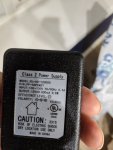
The power supply is working , I had a 12 v plug laying around I am using. I am really new to this , a picture of what the regulator looks like. What setting do I use on my multimeter. Commercial Electric MS8301B Auto Ranging Digital Multimeter Commercial Electric Ms8301b Auto Ranging Digital Multimeter - Google Search. Any help would be greatly appreciated! This is the power supply I am using.With your board I'd start with the power supply... nothing's going to work until you can get 5vdc out of the regulator.
Test the inputs/outputs of the two bridge rectifiers (BR1, BR2), and the output of the 5v regulator (U2). Then do the current check I mentioned above... if it's too high, pull those two socketed uln2803 chips (transistor arrays that drive the relays) and test current again. If it's still too high you'll want to look for shorts and start testing parts, and I would pull the lcd so I could then pull the comm chip. A thermal camera comes in handy at finding parts that draw too much juice - they heat up!
If you get the power supply working, with some fairly inexpensive tools you can sniff the outputs of the real time clock, the comm circuitry, and the lcd while you're at it. You can do a lot with these boards without ever hooking up the 18/24ac input.
I don't have any videos but I've posted a bunch of info here, probably more to come since we're all stuck at home
Tinkering with Electronics
Attachments
Hey,
The power supply I'm referring to is the on-board power supply... not your 12v wall wart. The Easytouch takes 12v from an external source, and has it's own power supply circuitry that provides 12vdc to the red/black on J20, AND generates a regulated 5vdc to run the microcontroller and all the on-board electronics. In a previous post you noted that you're not getting the correct voltage on J20... so the on-board power supply is the place to start.
You'll use the ac voltage setting to check the rectifier inputs, and the dc voltage setting to check the output of the rectifiers, 5v regulator, and most everything else on the board. You'll use the current (A) setting to measure current draw. I'd suggest googling for videos on how to operate that particular multimeter.
I don't have any particular online resources in mind as far as learning about electronics but the content is nearly limitless... again, google's going to be your friend here. Once you get familiarized with some of the basic concepts and components, you can start looking up particular part numbers to see how they work - like the LM1084 5v regulator. And it just keeps going from there. Good luck!
Thread Status
Hello , This thread has been inactive for over 60 days. New postings here are unlikely to be seen or responded to by other members. For better visibility, consider Starting A New Thread.