Pentair Easy Touch LCD Screen

Jun 5, 2010
27
New Jersey
Pool Size
20000
Surface
Plaster
Chlorine
Salt Water Generator
SWG Type
Pentair iChlor 30
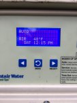
I opened my pool this year to a malfunctioning LCD screen (and 2 broken CVA-24 actuators. but I'll save that for a different thread)
I called Pentair and was told that I needed to replace the entire mother board on the panel.
I'm asking you guys for better advise!!! HA!
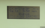
I've attached a picture of the bad screen.
Please tell me I don't have to spend $300-$500 on an entire mother board to fix this!!!

Thanks in advance
Lou ...
 
vg,

Well, it appears to me that the LCD just plugs into the main PCB, but the problem is that you can't buy just the LCD... If I knew I had to replace the whole thing anyway, I'd pop the LCD off the main board and flex it and reinstall it. Probably only a 10% chance of it working, but better than nothing...

Are you sure that you have two bad actuators or could it also be a problem with the EasyTouch itself? Did you pop one of the circuit breakers on the front panel??

Thanks for posting,

Jim R.
 
Sorry for the late post, but thought I'd capture this for others.

The LCD is replaceable if you can solder / desolder. The part is available for $5-15. I couldn't find the exact LCD so I found a compatible part but the screen was blue with white text (nice upgrade): Manufacturer: WinstarPart Number: WH1604A-TMI-JT. Original part was EW16400GLY from Emerging Displays. I couldn't find one in the US, so I bought the Winstar part on ebay. Worked perfect.

Pictures of the original LCD are in the links below. I wasn't too kind to it desoldering it.


https://photos.app.goo.gl/08Hc2SOsXMk6OgDs2

https://photos.app.goo.gl/fbJoA4hLjxKOGvao2
 
  • Like
Reactions: MyAZPool and JR1
2manybikes,

I really appreciate your post as I followed your guidance above and it the new display works great. Someone thought the original LCD was a touch screen and for half the season I could only see the top two lines. I waited to close down the pool and just had time to replace the display. My soldering is pretty poor and it took me a while to get the old one off / new one on but it works. And agree, the white on blue is a bonus upgrade.
 
Nice work lazy gardner!... would love to see a pic of that new white on blue display :)

I use a small handheld desoldering pump from Radio Shack to remove these displays, but if it's really stubborn I cut the 16-pin header with a dremel and desolder the pins 1 by 1 - it's actually a lot easier that way but of course you do have to replace the header.
 
Hi Ogdento, it was a struggle taking the old one off even with a pump. I had thought about cutting the pins but with my lacking in skills in the area, I figured I would create a bigger problem by doing so. Here's a photo of the display (pool is shutdown for the season as a little cool right now).

WhiteBlueDisplay.jpg
 
Kudos, that is great work! I don't know why - I mean it's just a different color - but I definitely agree that the white on blue looks very cool!!

... and better still, for 10 bucks and some of your time there's one more EasyTouch board kept out of a land-fill ;)
 
Hey LazyGardener & 2manybikes! Thanks for sharing both of your experience. I am signing myself up for the same project as half of my display is gone.

I as well am not a soldering expert, and wanted to ask more about your experience on taking the old display off and putting the new one on.

Did you individually have to go pin by pin?
What was the toughest part of the process?
Any special solder that you used?

Just trying to learn as I just ordered my new display and I should have it soon. Hoping this will save me more than $400! :)

Thanks!
 
Hey Ricky,
I've removed a dozen or so of these displays... I go pin by pin, using basic soldering tools (you don't need a fancy de-soldering station for these)...

IMG_20190125_121020378.jpg
De-soldering "through hole" parts with just an iron (the blue one on the left) and a de-soldering pump (the gold thing in the middle) is do-able, but can be a pain because you often only have access to the solder joint itself... you have to heat the joint and then very quickly move the iron and get the pump in place to suck out the solder.

But, on the ET controller shown below you can see the header that connects the LCD to the main board... in a response above I suggested cutting the header pins, but there's an easier way that doesn't destroy the header...

IMG_20190125_120749759.jpg
You can heat the header pin between the two boards, as close to the LCD as you can, and then use the pump on the top of the LCD solder joint to suck out the solder. This allows you to heat and pump simultaneously... as soon as the solder melts you hit the pump plunger.

A few other tips...
- flux is your friend (electronics flux, not plumbing!)... it helps the solder melt and flow. put a bit of flux on the solder joints and header pins before de-soldering
- add new solder to stubborn joints... sometimes "old" solder doesn't melt/flow easily, and a bit of new solder helps things along
- use IPA (isopropyl alcohol) to thoroughly clean off any flux residue from the main board, and repeat the cleaning when re-assembly is complete.

Hope that is useful info,

Tom
 
  • Like
Reactions: JR1 and rfricky1414
Hey Ricky,
I've removed a dozen or so of these displays... I go pin by pin, using basic soldering tools (you don't need a fancy de-soldering station for these)...

View attachment 92396
De-soldering "through hole" parts with just an iron (the blue one on the left) and a de-soldering pump (the gold thing in the middle) is do-able, but can be a pain because you often only have access to the solder joint itself... you have to heat the joint and then very quickly move the iron and get the pump in place to suck out the solder.

But, on the ET controller shown below you can see the header that connects the LCD to the main board... in a response above I suggested cutting the header pins, but there's an easier way that doesn't destroy the header...

View attachment 92399
You can heat the header pin between the two boards, as close to the LCD as you can, and then use the pump on the top of the LCD solder joint to suck out the solder. This allows you to heat and pump simultaneously... as soon as the solder melts you hit the pump plunger.

A few other tips...
- flux is your friend (electronics flux, not plumbing!)... it helps the solder melt and flow. put a bit of flux on the solder joints and header pins before de-soldering
- add new solder to stubborn joints... sometimes "old" solder doesn't melt/flow easily, and a bit of new solder helps things along
- use IPA (isopropyl alcohol) to thoroughly clean off any flux residue from the main board, and repeat the cleaning when re-assembly is complete.

Hope that is useful info,

Tom

Tom,

Appreciate this level of detail as this will help! We are planning on doing it next week so I will update you on our progress!

Thanks again!

- Ricky
 

Enjoying this content?

Support TFP with a donation.

Give Support
View attachment 92399
You can heat the header pin between the two boards, as close to the LCD as you can, and then use the pump on the top of the LCD solder joint to suck out the solder. This allows you to heat and pump simultaneously... as soon as the solder melts you hit the pump plunger.

A big thank you to member 2manybikes!

I stumbled upon this thread by accident while searching for an remote display/interface solution for my panel.

I was mad over the fact that the replacement board costs $500.00 and thought I can purchase an remote monitoring system for less than the cost of the board since the display is the only faulty part.. My display would fail when outside temps are over 70 degrees.

I had to wake up early in the morning in order to read the display.

I did what Tom advised, BUT, place the "needle" of the soldering iron between two pins and heat both at the same time.
You can vacuum/desolder two contact points at once and you don't have to worry about keeping the needle steady on one pin.

The blue display is actually BETTER than the OEM and IMO is what should of come with the panel.
 
Nice work JR! And great additional trick with the soldering iron.

Would you say the blue display is equally readable in daylight (as the green one was)?
 
I just wanted to add my thanks to everyone that has contributed to this thread. I had the same issue with my screen and did not want to shell out a few $100 for a new board. So I ordered the blue screen and a soldering kit and got to work. All of the hints are useful but I will say that it just takes a little patience. Even after it looked like I sucked all of the solder out from each pin, there must have been a little left in there because it took a little bit of careful force (rocking back and forth) to finally dislodge the old screen. But, the blue screen is in now and it looks great. Thanks again to all for sharing your experiences and advice.
 
Nice work Chaddy! I just pulled off a display today and these can definitely be a pain!

After I suck out all the solder I can, if the pin is still "stuck" I grab it in the "middle" (between the two boards) with needle nose pliers and gently "rock" it while I hit the top pad with the iron... I keep rocking it after I pull the iron so it doesn't stay joined. I make sure I can slightly rock all the pins before I try to pull the display - otherwise you could rip out the copper through-hole plating.
 
  • Like
Reactions: Chaddy and MyAZPool
With the tips above and a little force, I managed to remove the old display. I could not get the Winstar display, so instead replaced the screen with this one from Crystalfonz: Blue 16x4 Edge-Lit Character LCD from Crystalfontz. Specs seemed to be fine, but I'm an amateur, so maybe I got the wrong part. When I powered up the unit, the display lights up, but no characters display. I did not solder the pins... could this be why? I don't want to spend the time soldering the pins if I don't have the right part, or if the connection to the LCD display is broken. The board still seems to work, as my pump started on time this morning, but no display.
 
I simply saw thru the pins, then desolder the remaining half of each pin one by one from the motherboard.

I have tried a few different types of screens. Not all of them work. Item pictured in that link looks spot on. You can only know for sure by testing. I think you need to solder it in place.

I do have a modification, that allows the screen to "plug in" instead of being soldered. But it requires more parts...
 
Thanks. Do you have a link to a screen that has worked for you? Though the one I bought may be fine, and I just need to solder. I thought that with the plastic connectors and pins, the connection would be fine and I could skip soldering, but maybe not. I'm not sure I have the skills to add a dot of solder to each pin without creating a short. Removing the old screen just required patience and brute force, not much finesse.
 

Enjoying this content?

Support TFP with a donation.

Give Support