Pentair Colorsync Wiring

Dreaves

Active member
Aug 9, 2019
36
Lake worth fl
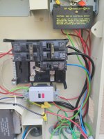
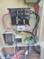
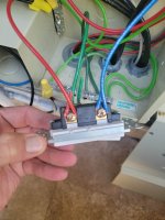
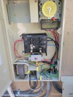
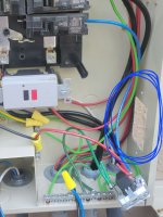
Hello All, trying to wire in a pentair colorsync controller. Doesnt seem that i have a neutral (common) wire in the box? I see white, but then it connects to black and blue (at the light transformer i assume). Also see white going to a line strip in the top left of the box.

This is a new build, but electric company would not install the switch we wanted.

Please help if you can
 

Attachments

  • 326171369_529773652479277_8495665915691911262_n.jpg
    326171369_529773652479277_8495665915691911262_n.jpg
    376 KB · Views: 14
  • 326169734_498339362438238_3769880821632534049_n.jpg
    326169734_498339362438238_3769880821632534049_n.jpg
    376.8 KB · Views: 14
  • 326217495_863238205011434_2436680158906864521_n.jpg
    326217495_863238205011434_2436680158906864521_n.jpg
    297 KB · Views: 13
  • 326210398_1264508864274524_5345503054860270925_n.jpg
    326210398_1264508864274524_5345503054860270925_n.jpg
    354.8 KB · Views: 15
The Colorsynch Controller connects to the high voltage side of the transformer.

Your fingers on the white, blacks, and blue wires are the low voltage side. The controller does not connect there.

The transformer is in the lower left of the electrical box. Coming out of the top holes are the white neutral wire connected to the neutral bar and a blue wire which is wire nutted to a red hot wire connected to the GFCI outlet. Those are the red and white wires shown on the diagram below.

Your electrician did some interesting stuff. Instead of using a standard 20A GFCI CB for your pool pump they sued a non-GFCI CB and a separate GFCI box.

Where do you intend to m out the Color Synch Controller?

F88748BF-5153-460F-9913-2FD05B8FA420.png
 
The Colorsynch Controller connects to the high voltage side of the transformer.

Your fingers on the white, blacks, and blue wires are the low voltage side. The controller does not connect there.

The transformer is in the lower left of the electrical box. Coming out of the top holes are the white neutral wire connected to the neutral bar and a blue wire which is wire nutted to a red hot wire connected to the GFCI outlet. Those are the red and white wires shown on the diagram below.

Your electrician did some interesting stuff. Instead of using a standard 20A GFCI CB for your pool pump they sued a non-GFCI CB and a separate GFCI box.

Where do you intend to m out the Color Synch Controller?

View attachment 469673
Thank you. I planned on mounting it on the right where the old switch was. In this circle area.

The blue wire out of the transformer actually goes to nothing. It ends at the wire connector, but nothing is connected to it. Both those blue and yellow wires coming out of the top end at a wire connector and nothing is connected. You can kinda see it in the attached picture.

We originally had a lutron switch there, but they removed it and said it would not work. Maybe those wires went to that switch?
 

Attachments

  • 20230118_161635.jpg
    20230118_161635.jpg
    364.5 KB · Views: 6
See the pic below. Red marks pointing to the hot and neutral wires that power the light transformer.

55053D59-86F5-475B-B1F4-3768CB514381.jpeg
 
See the pic below. Red marks pointing to the hot and neutral wires that power the light transformer.

View attachment 469738
Thanks so much. So on the back of thecontroller i have load, neutral, line.

Load - is the red wire from the transformer?
Line - the blue from the breaker?
Neutral - run a white wire from the strip block to the neutral side of the switch?

Thanks again
 
Thanks so much. So on the back of thecontroller i have load, neutral, line.

Load - is the red wire from the transformer?
Line - the blue from the breaker?
Neutral - run a white wire from the strip block to the neutral side of the switch?

Thanks again
Neutral from transformer and from controller must be wire nutted together with a pig tail that connects to the neutral bar.
 
Have a concern the incoming power feeder wires maybe undersized.
What is the gauge of the black wires feeding the bottom of the circuit busses. It will be on the wires.
 
Thread Status
Hello , This thread has been inactive for over 60 days. New postings here are unlikely to be seen or responded to by other members. For better visibility, consider Starting A New Thread.