Hello,
I am trying to replace a regular wall switch with the Pentair Color Sync Controller.
My current setup is:
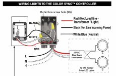
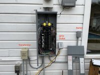
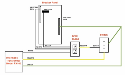
1 x 120 v light & 1 x 12v light > Transformer > Breaker panel > Wall switch
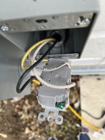
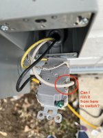
The wall switch has 3 wires going in
Hot | Neutral | Ground
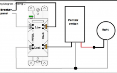
I tried the following wiring on the Pentair Color Sync Controller :
Hot wire to Line
Neutral Wire to Neutral
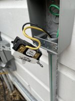
Ground wire I left connected to the wall switch housing.
The controller is lighting up and connecting to wifi but it's not sending any signals to my lights.
Both lights are off.
I also tried the following wiring:
Hot wire to Line
Neutral Wire to Load
Ground wire I left connected to the wall switch housing.
Still didnt work.
Pentair support line was no help and kept telling me to get a licensed electrician to install it.
If anyone is familiar with this, I'd really appreciate the help.
I am trying to replace a regular wall switch with the Pentair Color Sync Controller.
My current setup is:
1 x 120 v light & 1 x 12v light > Transformer > Breaker panel > Wall switch
The wall switch has 3 wires going in
Hot | Neutral | Ground
I tried the following wiring on the Pentair Color Sync Controller :
Hot wire to Line
Neutral Wire to Neutral
Ground wire I left connected to the wall switch housing.
The controller is lighting up and connecting to wifi but it's not sending any signals to my lights.
Both lights are off.
I also tried the following wiring:
Hot wire to Line
Neutral Wire to Load
Ground wire I left connected to the wall switch housing.
Still didnt work.
Pentair support line was no help and kept telling me to get a licensed electrician to install it.
If anyone is familiar with this, I'd really appreciate the help.