One option to consider of decking / coping is: MSI Arterra Porcelain pavers.. I ended up going with this.. You can find some pics of this in the forum.. For this, you can do baserock + sand and set porcelain pavers on them (except for areas near dive boards / slides / anchors for ladder -- they need 6" concrete base, and mortar set porcelain pavers on top.
PB disappeared ->Half an owner build
- Thread starter hooraysimpsons
- Start date
You are using an out of date browser. It may not display this or other websites correctly.
You should upgrade or use an alternative browser.
You should upgrade or use an alternative browser.
We finally got some paver base around the pipes and backfilled trenches some before a heavy rain. Still need to do the rough grading better. We've gotten one pool builder quote finally to take over the job completely but we are still moving forward with individual pieces in the mean time. Still having trouble getting plaster quotes but hopefully as we get closer to being ready for them it will work out.
New questions:
1. Any with pictures of travertine/marble coping with (concrete) paver decking? Not seeing a lot of pictures online to help my wife visualize
2. Any recommendations for online ordering SR Smith slide/ladder/handrail? (I've read existing threads so if you've commented I've likely read it and you don't have to repeat yourself.)

The thread I am going to share with you was put together to show off the plaster BUT you can see their coping and decking. I am hopeful you can find a pic that will help your wife see what you are thinking about.
 www.troublefreepool.com
Pool Finish and Color Viewing Room...PICTURES & details only please
This is our attempt at having one place that we can view the finished product of various Plaster/Pebble/Quartz/Vinyl/FG/etc. pool finishes. Simply attach a good pic looking down at the steps and another one looking at the deep end to share how it looks at different depths. Make sure to share the...
Last edited by a moderator:
Thank you. That thread was helpful in general. I didn't see anyone with travertine/marble coping then concrete pavers. We like the color combination we could create doing that but I'm worried the texture differences in material would look weird. Maybe it wouldn't be so different than those with travertine coping and poured concrete decks.The thread I am going to share with you was put together to show off the plaster BUT you can see their coping and decking. I am hopeful you can find a pic that will help your wife see what you are thinking about.
Pool Finish and Color Viewing Room...PICTURES & details only please
This is our attempt at having one place that we can view the finished product of various Plaster/Pebble/Quartz/Vinyl/FG/etc. pool finishes. Simply attach a good pic looking down at the steps and another one looking at the deep end to share how it looks at different depths. Make sure to share the...www.troublefreepool.com
Think of it more of accenting the pool with the different material. It is a great look!
Hopefully a quick question to help finish ordering all my 'parts'. Planning to use the fantastic royal marble coping from NPT. For spanning the skimmer mouth it seems like best practice would be to still use an aluminum skimmer plate. Then that would ideally be attached to my bonding. Is they a specific method of attaching the #8 wire to the plate that is approved? I haven't seen a specific clamp to connect to flat metal sheets but assume I can use a conduit clamp with holes drilled through the aluminum sheet. However, that would be chipper out extra gunite and potentially the underside of the coping.
AQUA~HOLICS
In The Industry
Sorry, but I haven’t seen that plate used before, possibly the manufacturer has details on how to attach the bonding wire to the plate, plates are not common in my area.
Thank you for responding. Maybe this 'part' isn't as neccessary as I thought it was.Sorry, but I haven’t seen that plate used before, possibly the manufacturer has details on how to attach the bonding wire to the plate, plates are not common in my area.
Example part: SkimJim™ 8" x 24" Aluminum Skimmer Support Plate
My understanding is it would be helpful to support the coping across the skimmer mouth. I am getting the 12x24 coping from NPT https://www.nptpool.com/hardscapes/natural-stone/marble-stone/fantastic-royal/
I was thinking the part would be helpful based on threads such as:
Need advice: Fix Coping Over Skimmer
The pool is 15 years old and the coping has held up this long..but my pool guy must have stepped on the edge of the pool coping over the skimmer which caused it to pop loose. Now it leans down--see pics. Would you just chip away the cement and redo it as is? Or should I have a stone place cut...
I couldn't find anything authoritative on the coping's ability to span a certain length unsupported (and then support the weight of a person standing at pool edge). If the general builder consensus is that it can support that weight then I can just make sure my coping pieces are centered over the skimmer mouth.
I have a new question now. The PB that left did 2inch PVC through the gunite for all returns/lights, they did not leave enough of a 'hollow out' in the gunite around the pipes to add a coupler. My plan was to use the slip in type return eyeballs (the ones held in by friction). However, given my distrust of their work done so far I was pressure testing all my plumbing and electrical conduits. The PVC pip on one of the returns burst right as it was exiting the gunite on the pool water side. I'm not sure why a pipe would fail at that pressure but it comes out of the tanning ledge where workers were going in and out during gunite install so maybe it got stepped on or something.
The problem/question: I should still be able to use a 2inch PVC pipe extender and a slip eyeball return for final install without problem. But that doesn't leave me with a good method to do the pressure testing. If I add a coupling and length of piper after the extender to do pressure testing, any reason I cannot cut this flush with plaster level and then use slip fitting? If I chip out gunite to get a normal coupling on my incoming 2 inch line, I would probably want to go ahead and use an adapter to allow the more common threaded eyeball return but I'm having trouble visualizing how to do that and end up at the correct height. The pipe broke ~1inch below surface of the gunite.
Edit for my question: I think doing a normal coupling with a 2 inch to 1 1/2 inch threaded bushing would actually end up at the correct height for plaster. However, that requires chipping out the gunite around the pipe enough to allow a coupling to be placed. Is chipping out that much gunite a problem (would be a little over 2 inches depth)?
Edit 2: I have the Jandy Nicheless lights. Best I can tell with the 2inch PVC penetrations I am going to need to do a coupling with 2 inch to 1 1/2 inch threaded bushing anyways for those locations anyways. So I'm going to need chip out some gunite at all those spots. So I guess that'll be the plan for the repair noted above. Any input still appreciated.
Thanks all in advance
Last edited:
I appear to have another new problem. Finally got around to pressure testing the conduits for the lights after I learned they hold water. Seems they all have a small leak somewhere, slow but present. It seems I don't have many options:
1. Dig it all up and put in new conduit
2. Only dig up near each pool light. Run conduit that is watertight to nearby junction box and use the leak conduit for the rest of the path
Doesn't seem available -3. Use 'dry' nicheless light, please correct me if I'm wrong
Not a good option long term -4. Try to add watertight seal around cable on backside of gunite penetration. Makes service hard since cannot pull wire and would need to drain some to replace. However, if I have a paver deck would it be serviceable with digging up deck each time?
Also not dry - 5. Look like Hayward has some pretty shallow niche lights but I think they are still wet. Whats the smallest dry niche light that maybe I can retrofit
Other options?
Thanks
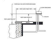
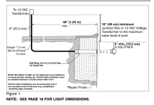
Pictures can help here. How are you pressure testing? Wet conduit should be run to a J-box in deck (short run), and then branch out to others. Some examples below -- make sure to properly bond the niche and follow all the code.I appear to have another new problem. Finally got around to pressure testing the conduits for the lights after I learned they hold water. Seems they all have a small leak somewhere, slow but present. It seems I don't have many options:
1. Dig it all up and put in new conduit
2. Only dig up near each pool light. Run conduit that is watertight to nearby junction box and use the leak conduit for the rest of the path
Doesn't seem available -3. Use 'dry' nicheless light, please correct me if I'm wrong
Not a good option long term -4. Try to add watertight seal around cable on backside of gunite penetration. Makes service hard since cannot pull wire and would need to drain some to replace. However, if I have a paver deck would it be serviceable with digging up deck each time?
Also not dry - 5. Look like Hayward has some pretty shallow niche lights but I think they are still wet. Whats the smallest dry niche light that maybe I can retrofit
Other options?
Thanks

I think, it is normal practice to chip-out near the pipe, and pack with hydraulic cement before plastering. Other experts can chime in as well.Edit for my question: I think doing a normal coupling with a 2 inch to 1 1/2 inch threaded bushing would actually end up at the correct height for plaster. However, that requires chipping out the gunite around the pipe enough to allow a coupling to be placed. Is chipping out that much gunite a problem (would be a little over 2 inches depth)?
Thank you. I'll chip out the gunite dig outs more to allow for a coupling to be installed.I think, it is normal practice to chip-out near the pipe, and pack with hydraulic cement before plastering. Other experts can chime in as well.
New questions: How big of a concrete pad to place for a handrail and ladder being installed in a paver deck? I called SR Smith and they had no guidance. I have purchased 6 inch deep anchors to allow for a concrete pad under the pavers but I don't know how big (wide) or deep would be recommended to counteract weight on the ladder/handrail.Pictures can help here. How are you pressure testing? Wet conduit should be run to a J-box in deck (short run), and then branch out to others. Some examples below -- make sure to properly bond the niche and follow all the code.
On
View attachment 638786View attachment 638787
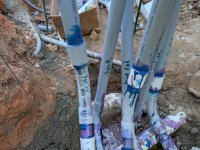
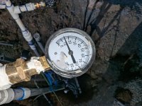
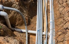
Follow up. Hello. I thought I had it fixed but maybe not. I dug up the conduits for several of the lights near where they branched to the light that seemed to have the biggest leak. I ran all near conduit to the light and added a 'stub up' for two others which meant I was eliminating about half the previously installed conduit from the equation. I pressure tested and everything held steady for ~24 hours. Now that I've buried it all again, the pressure is dropping on my tests. Pictures of test setup and new conduits, using water.
For the ladder, you can follow this:
Key things: Don't forget bonding the anchors back to the grid, ensure proper drainage holes for the anchor (meaning don't block the drain hole with concrete), and follow the right setback for the product you have chosen. In terms of the dimensions of the pad, unlike dive boards ladders / rails are simpler -- just like a footing for a post. So I would give at least 1 to 1.5 feet on either side of anchor, and at least 18" (36" x 18").
Sorry to say that the plumbing work for electrical looks pretty bad -- was this actually done by a pro? It should be a pretty simple SCH80, heat-bended without any joints rising up to a J-box.. I am also not sure if pressure testing conduit is a norm -- mostly we avoid any joints till the J-box, and main leak area is near niche. I suggest getting some pro help in solving this.
Thank you for your help so far.For the ladder, you can follow this:
Key things: Don't forget bonding the anchors back to the grid, ensure proper drainage holes for the anchor (meaning don't block the drain hole with concrete), and follow the right setback for the product you have chosen. In terms of the dimensions of the pad, unlike dive boards ladders / rails are simpler -- just like a footing for a post. So I would give at least 1 to 1.5 feet on either side of anchor, and at least 18" (36" x 18").
Sorry to say that the plumbing work for electrical looks pretty bad -- was this actually done by a pro? It should be a pretty simple SCH80, heat-bended without any joints rising up to a J-box.. I am also not sure if pressure testing conduit is a norm -- mostly we avoid any joints till the J-box, and main leak area is near niche. I suggest getting some pro help in solving this.
Regarding the anchors, I was following those instructions which made me look into using a 4 inch thick pad for easy drainage underneath. Then I read some other comments and was planning a 2x2 or 2x3 ft for the handrail and then 2x5 for ladder (include both anchors together). But then 2ftx2ftx4inch seemed a little small for a handrail with someone might lean on/hang from. If insufficient, it'd be easier to make a wider pad but open to suggestions either way.
I did setup bonding.
The picture shows my work to add the individual pressure testing in an attempt to identify where I was losing the pressure (not a pro) but that area isn't leaking based on direct visualization. I am slowly getting subs setup to take over work but I was just wanted to know what areas needed dug back up or not.
My lights a nicheless.
PB had 2 inch PVC going through gunite then used bushings to get do to 1 inch gray sch40 conduit. This was run all the way to the equipment pad so could not be a single piece. These did have heat bends to go around the pool corners. The bell ends at least had PVC cement used but I could not see any purple to determine if primer used. Picture below shows the connection to PVC, heat bends and bell end connections.
My understanding is these conduits would just be ~1psi from just gravity effects while in use so maybe pressure testing wasn't necessary but I wanted to check the PB's work. When I pressure tested the whole system I had obvious leaks that I isolated down to the conduits for lights. The testing has improved since running some new lines but I still see drops in two of them. Goes from 20psi to ~12-15 overnight.
Should I just call that good enough?
Any concern that it is all sch 40 instead of 80?
If in doubt, make it wider .. I did do 6" depth for the concrete though -- had a 2" pvc coupling filled with gravel underneath the anchors to prevent drain holes being plugged, and poured concrete. Also ensure to install the foam expansion joint (to isolate this pad from your coping).
SCH40 is fine. Looks like all the lights routed back to the equipment pad, creating more joints before going to J-box. I don't have experience with this and other forum members can potentially chime-in to help. In my mind, I was thinking it should be a straight run to a J-box (for the wet portion), and then a separate wiring conduits (normal buried electricals) connecting multiple of the J-boxes along with landscape lights. Also, don't worry about my comment on the pressure testing hookup -- TBH I started like this and improved now (all you need is some practice to prevent the run-off with primer, right amount of joint cement & wipe-off excess with a paper towel immediately).
SCH40 is fine. Looks like all the lights routed back to the equipment pad, creating more joints before going to J-box. I don't have experience with this and other forum members can potentially chime-in to help. In my mind, I was thinking it should be a straight run to a J-box (for the wet portion), and then a separate wiring conduits (normal buried electricals) connecting multiple of the J-boxes along with landscape lights. Also, don't worry about my comment on the pressure testing hookup -- TBH I started like this and improved now (all you need is some practice to prevent the run-off with primer, right amount of joint cement & wipe-off excess with a paper towel immediately).


