guinness

Well-known member
May 3, 2019
1,271
California
Pool Size
23000
Surface
Plaster
Chlorine
Liquid Chlorine
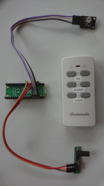
If you're using njsPC to monitor and control your Pentair EasyTouch, IntelliTouch or IntelliCenter and wanted a wireless remote like the QuickTouch II for under $50 then look no further.
pico_rc.png

There are several generic RF outlets and switches that use the 433MHz frequency for remote control and are manufactured by companies including
BESTTEN, BN-LINK, Dewenwils, Etekcity and Syantek. The wireless remotes use LPD/SRD signals which can be picked up with a compatible receiver.

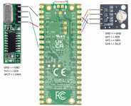
You can buy a cheap 433Mhz Wireless Remote and a Raspberry Pi Pico W to process the signals using a Superheterodyne Receiver and a 3 Color LED for a status indicator. No soldering is required as Dupont Wires can be used with the PCB header pins as shown in the previous image. See the diagram below for wiring up the modules:
pico_pins.png

The software side will be detailed in the next post. Prior to this you will need to install Thonny, Python IDE for beginners on your PC and MicroPython - Python for microcontrollers on the Raspberry Pi Pico which is described here.
 
Last edited:
  • Like
Reactions: ogdento
The following software code will listen to signals from the 433Mhz remote and if a button is pressed on the remote it can send a HTTP request to njsPC and take the appropriate action on the automation system.

Below are Python files that will need to be saved onto the Raspberry Pi Pico using Thonny. The file name is shown at the top of the code section and a short description about the contents afterwards.

boot.py
Python:
import network

def do_connect(ssid, pwd):
    sta_if = network.WLAN(network.STA_IF)
    if not sta_if.isconnected():
        print('connecting to network...')
        sta_if.active(True)
        sta_if.connect(ssid, pwd)
        while not sta_if.isconnected():
            pass
    print('network config:', sta_if.ifconfig())
 
# Attempt to connect to WiFi network
do_connect('SSID', 'PWD')
This code will get run immediately after booting the Pico. It will establish the connection to your wireless router, so you will have to change the final line to include both the SSID of your WiFi AP and the respective password.

rpi_rf.py
Python:
"""
Receiving 433/315Mhz signals with low-cost GPIO RF Modules on a Raspberry Pi.
Modified code for Raspberry Pi Pico, original at github.com/milaq/rpi-rf
"""

import config
import time
from machine import Pin
from collections import namedtuple

MAX_CHANGES = 67

Protocol = namedtuple('Protocol',
                      ['pulselength',
                       'sync_high', 'sync_low',
                       'zero_high', 'zero_low',
                       'one_high', 'one_low'])
PROTOCOLS = (None,
             Protocol(350, 1, 31, 1, 3, 3, 1),
             Protocol(650, 1, 10, 1, 2, 2, 1),
             Protocol(100, 30, 71, 4, 11, 9, 6),
             Protocol(380, 1, 6, 1, 3, 3, 1),
             Protocol(500, 6, 14, 1, 2, 2, 1),
             Protocol(200, 1, 10, 1, 5, 1, 1))

class RFDevice:
    """Representation of a GPIO RF device."""

    def __init__(self, gpio = None, rx_tolerance=80):
        """Initialize the RF device."""
        self.gpio = gpio
        self.rx_enabled = False
        self.rx_tolerance = rx_tolerance
        # internal values
        self._rx_timings = [0] * (MAX_CHANGES + 1)
        self._rx_last_timestamp = 0
        self._rx_change_count = 0
        self._rx_repeat_count = 0
        # successful RX values
        self.rx_code = None
        self.rx_code_timestamp = None
        self.rx_proto = None
        self.rx_bitlength = None
        self.rx_pulselength = None

    def cleanup(self):
        """Disable RX and clean up GPIO."""
        if self.rx_enabled:
            self.disable_rx()
        print("Cleanup")

    def enable_rx(self):
        """Enable RX, set up GPIO and add event detection."""
        if not self.rx_enabled:
            self.rx_enabled = True
            self.gpio = Pin(config.RX_PIN, Pin.IN, Pin.PULL_DOWN)
            self.gpio.irq(handler=self.rx_callback, trigger=Pin.IRQ_FALLING | Pin.IRQ_RISING)
            print("RX enabled, pin: " + str(config.RX_PIN))
        return True

    def disable_rx(self):
        """Disable RX, remove GPIO event detection."""
        if self.rx_enabled:
            self.gpio.irq(None)
            self.rx_enabled = False
            print("RX disabled")
        return True

    def rx_callback(self, gpio):
        """RX callback for GPIO event detection. Handle basic signal detection."""
        timestamp = time.ticks_us()
        duration = timestamp - self._rx_last_timestamp
        if duration > 5000:
            if abs(duration - self._rx_timings[0]) < 200:
                self._rx_repeat_count += 1
                self._rx_change_count -= 1
                if self._rx_repeat_count == 2:
                    for pnum in range(1, len(PROTOCOLS)):
                        if self._rx_waveform(pnum, self._rx_change_count, timestamp):
                            break
                    self._rx_repeat_count = 0
            self._rx_change_count = 0

        if self._rx_change_count >= MAX_CHANGES:
            self._rx_change_count = 0
            self._rx_repeat_count = 0
        self._rx_timings[self._rx_change_count] = duration
        self._rx_change_count += 1
        self._rx_last_timestamp = timestamp

    def _rx_waveform(self, pnum, change_count, timestamp):
        """Detect waveform and format code."""
        code = 0
        delay = int(self._rx_timings[0] / PROTOCOLS[pnum].sync_low)
        delay_tolerance = delay * self.rx_tolerance / 100

        for i in range(1, change_count, 2):
            if (abs(self._rx_timings[I] - [/I]delay * PROTOCOLS[pnum].zero_high) < delay_tolerance and
                abs(self._rx_timings[i+1] - delay * PROTOCOLS[pnum].zero_low) < delay_tolerance):
                code <<= 1
            elif (abs(self._rx_timings - delay * PROTOCOLS[pnum].one_high) < delay_tolerance and
                  abs(self._rx_timings[i+1] - delay * PROTOCOLS[pnum].one_low) < delay_tolerance):
                code <<= 1
                code |= 1
            else:
                return False

        if self._rx_change_count > 6 and code != 0:
            self.rx_code = code
            self.rx_code_timestamp = timestamp
            self.rx_bitlength = int(change_count / 2)
            self.rx_pulselength = delay
            self.rx_proto = pnum
            return True

        return False
This code is from the GitHub repo rpi-rf that has been modified to work with MicroPython. It processes the 433MHz signals from the wireless remote and identifies each button that is pressed with a seven digit number. You will need to make a note of these numbers when the corresponding button is pressed on the remote.

main.py
Python:
import time
import machine
import rpi_rf
import urequests

RX_PIN=27
RED_PIN=2
GRN_PIN=3

API_URL='http://raspberrypi:4200/state/circuit/setState'
DICT_BTNS={
    #4281603: { 'id': 5, 'isOn': 1 },
    #4281612: { 'id': 5, 'isOn': 0 }
}

def remote_listen():
    rfdevice = rpi_rf.RFDevice()
    rfdevice.enable_rx()

    timestamp = None
    lastcode = 0

    ack_led = machine.Pin(GRN_PIN, machine.Pin.OUT)
    nak_led = machine.Pin(RED_PIN, machine.Pin.OUT)

    while True:
        if rfdevice.rx_code_timestamp != timestamp:
            if rfdevice.rx_code != lastcode or time.ticks_diff(rfdevice.rx_code_timestamp, timestamp) > 5000000:
                lastcode = rfdevice.rx_code
                print(str(rfdevice.rx_code) + ' [pulselength ' + str(rfdevice.rx_pulselength) + ', protocol ' + str(rfdevice.rx_proto) + ']')
                if lastcode in DICT_BTNS:
                    resp = urequests.put(API_URL, json=DICT_BTNS[lastcode])
                    if resp.status_code == 200:
                        ack_led.on()
                        time.sleep(0.5)
                        ack_led.off()
                    else:
                        nak_led.on()
                        time.sleep(0.5)
                        nak_led.off()
                resp.close()
            timestamp = rfdevice.rx_code_timestamp

# Start listening for remote signals
remote_listen()
This is the main application code that will listen for buttons being pressed on the wireless remote using the rpi_rf code. If you have wired up the modules as detailed in the previous post you can leave the values for the variables RX_PIN, RED_PIN & GRN_PIN as they are. Otherwise change appropriately.

For the variable API_URL you will need to change raspberrypi to the hostname or IP address of the device running njsPC. This is typically the same host as the dashPanel web client.

Finally you will need to set the dictionary values for the DICT_BTNS variable. This maps the button pressed to the JSON payload which will be sent to the /state/circuit/setState endpoint on nJSPC. It comprises of the circuit id that you want to change and the value 1 or 0 to turn on or off.

To get the button ids you will first need to run the program whilst connected to Thonny using the REPL interface. You may have to press CTRL+D which is a keyboard shortcut for "Send EOF / Soft reboot". Once you see output in the console you will need to press each button on the remote in turn and note the corresponding number. The example below is for when two buttons were pressed for on and off.

MPY: soft reboot
network config: ('192.168.1.210', '255.255.255.0', '192.168.1.1', '8.8.8.8')
RX enabled, pin: 27
4281603 [pulselength 167, protocol 1]
4281612 [pulselength 166, protocol 1]

You will then need to stop the program by pressing CTRL+C and edit main.py to change the value for the DICT_BTNS variable. The two existing lines are provided as an example and are ignored since they are preceded with a # symbol. You can uncomment those by removing the # symbol and substituting the button numbers that you previously recorded (add additional lines where necessary). You will also need to change the circuit number from 5 to whatever circuit number you wish to turn on and off. Once you've finished adding all the buttons and the respective actions you can save the file with the updates.
 
Last edited:
Since the file is named main.py that means that this code will automatically run after boot.py has completed. So by restarting the device using "Stop/Restart backend" in Thonny or by simply plugging the USB connector into a power supply the program will run and listen for button presses from the wireless remote control.

If everything it working correctly you should now be able to press a button on your remote and see the LED light either flash green or red. If it flashes green it means that the HTTP request to njsPC completed successfully and you should be able to go into dashPanel web client using a web browser to see if the circuit was turned on or off accordingly. If the LED flashed red then it means that the HTTP request failed. This could be a case of a bad configuration in the Python code or a problem with njsPC.

Hopefully you were able to get a successful result and control your automation system from the wireless remote control. It was a fun project to work on and I hope that others will be able to make use of it. Not only is it cheaper than a Pentair wireless remote it also gives you complete control over how button presses are acted upon by customizing the Python code.
 
Last edited:
Thread Status
Hello , This thread has been inactive for over 60 days. New postings here are unlikely to be seen or responded to by other members. For better visibility, consider Starting A New Thread.