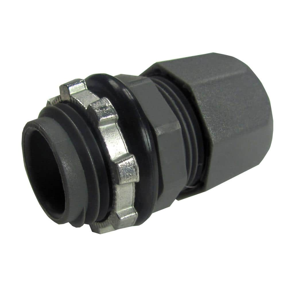
You will need to purchase one of those electrical conduit connectors that fits to those knockout holes. Knock out the tab, feed the wire through the connector and screw the connector in the hole.
Do you have a VS pump or a single speed pump?
When looking at the power relay, the 4 connections are Line 1, Load 1, Line 2, Load 2 from left to right
When you loosen the screw, there should be room to insert wire ends on each side of the screw under that tab. You want to ensure the wire is fully inserted with no strand sticking out.
If you have a VS pump - it is recommended to have the VS pump on constant power, you mention Jandy ePump so you can confirm that.
Line 1 will have 2 wires - the black main power and the blue VS pump
Load 1 will have 2 wires - the heater and the SWCG
Line 2 will have 2 wires - the black main power and the blue VS pump
Load 2 will have 2 wires - the heater and the SWCG
The pump will operate per your schedule on the iAquaLink program.
When it turns off, power will also be turned off at the relay (load side) to cut power to your Heater and your SWCG
Dont forget to connect the ground wires.
Also, switch off your circuit breaker to the whole system when wiring.
You may want to tidy up some of your wiring - lots of exposed wire that should be inserted properly behind each screw.
Edit - you need to also link your bond wire to your controller. CircuPool has a lug on the side. So get the proper sized wire and link it from either your pump or heater bond wire connection to the controller.
Edit - if you do have an Jandy ePump, you may want to review its manual. I remember reading that they may have a place to hook up a SWCG directly to the pump - where the wires attach to the pump motor. That may be easier for you. Not sure if that applies to all ePumps.
Edit - I looked at the manual for ePump and it was unclear if you could make the SWCG connection. It does have extra knock out tabs in the high voltage side of the pump electrical connection but no details on what can be connected to it.
I have a Pentair VS pump and how I indicated above is how I plan to hook up my SWCG in future.