Need help Wiring my Pureline VSP 2.7 HP (PL2626/PL2606) to my IC40 SWCG

patplh

0
LifeTime Supporter
Jul 29, 2009
210
Massachusetts
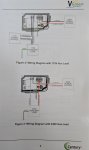
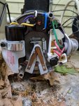
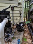
Hi, After much debate, we ordered the VSP Pureline PL2626 (salt friendly model) from inyopools to replace our single speed hayward super pump. We decided to DIY the install, but need a little help with the wiring for the Intellichlor IC40 (with Power Center). My current set up has the Hayward Super Pump and IC40/Power Center powered by our pool timer. I'd like to set it up so that my PL2626 is powered by the pool timer, but we'll set it as ON always and I want to connect my IC40 to the AUX power of the PL2626. The IC40 Power Center has 2 Red lines and 1 Green. I'm assuming the 2 Red are the L1 and L2 lines and the Green is the Ground line. Similarly, our Hayward Super Pump has 2 Red lines and 1 Green. I'm not clear on how to connect the Power Center to the AUX Power of the PL2626. Posting pictures of our current set up (PowerCenter and Pump), close up of our old Hayward Pump wiring and the wiring diagram for the PL2626 in hopes someone can provide guidance. Thanks so much!
Patty
 

Attachments

  • IMG_20190525_180357.jpg
    IMG_20190525_180357.jpg
    171.4 KB · Views: 19
  • IMG_20190525_165238.jpg
    IMG_20190525_165238.jpg
    530.6 KB · Views: 19
  • IMG_20190525_164439.jpg
    IMG_20190525_164439.jpg
    721.6 KB · Views: 14
P,

You would use Fig 3... 240 input to the pump and then 240 output to the SWCG..

Forget about color, just connect one Red to L1 input and the other Red to L2 input Then L2 goes to the SWCG and the L1 gets jumpered to the input side of the aux relay.. the output side of the relay gets connected the the L1 SWCG connection..

When the pump is running the relay is closed and the power is applied to the SWCG..

Jim R.
 
Thanks so much. Currently, both the green line from the SWCG and the Pump are connected to a line that goes to the timer (I think). Would that remain as is? or do I need to connect them differently - if so, how? :)
Thanks again @Jimrahbe

P,

You would use Fig 3... 240 input to the pump and then 240 output to the SWCG..

Forget about color, just connect one Red to L1 input and the other Red to L2 input Then L2 goes to the SWCG and the L1 gets jumpered to the input side of the aux relay.. the output side of the relay gets connected the the L1 SWCG connection..

When the pump is running the relay is closed and the power is applied to the SWCG..

Jim R.
 
Pat,

The green wire is the ground.. (marked as "Earth" in your new pump).. As long as the all the greens are connected together and each piece of equipment has a green wire connected, it will be just fine..

Thanks,

Jim R.
 
And don't forget to connect the bonding wire. There should be a metal lug on the outside of the pump case and IC power center for this bare copper wire.
 
Thanks @proavia for mentioning this - that was going to be next question :) It's already connected to the pump, IC power center and our booster pump (not used), so we'll plan to just remove from the old pump and reconnect to the new pump. Thanks again

Thank you @Jimrahbe for all the responses too! Really Appreciate it!!
Patty

QUOTE="proavia, post: 1622108, member: 80551"]
And don't forget to connect the bonding wire. There should be a metal lug on the outside of the pump case and IC power center for this bare copper wire.
[/QUOTE]
 
Thread Status
Hello , This thread has been inactive for over 60 days. New postings here are unlikely to be seen or responded to by other members. For better visibility, consider Starting A New Thread.