You can use one of of the relays for the actuator. Use a 24 vac transformer capable of handling 1 amp (shouldn't be hard to find). I did something similar for actuator control, but used different relay switches (link in sig).
This paragraph from the link explains how to make the connections:
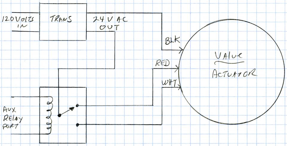
...Each valve actuator can be run in both directions off one relay. Each relay has three connections: Common (24 VAC power), NC (normally closed) and NO (normally open). The actuators have three connections. The black lead goes to the other side of the AC power. The other two actuator leads (red and white) power the valve in separate directions. One lead goes to NC and the other to NO. When power is shut off, the motor turns one way and when powered up, it turns the other way. A limit switch in the actuator cuts power to the motor when the valve reaches it's resting position.