
Jandy AquaPure No Chlorine Production, But No Error Codes
- Thread starter socalsharky
- Start date
You are using an out of date browser. It may not display this or other websites correctly.
You should upgrade or use an alternative browser.
You should upgrade or use an alternative browser.


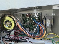
It can take 120 volts or 240 volts on the primary.
Show the label on the Transformer.
Check the voltage going into the transformer (Primary) and going out (Secondary.


The Primary has two sets of windings.
For 240 volts, they are in series.
For 120 volts, they are in parallel.


Show the label on the Transformer.
Check the voltage going into the transformer (Primary) and going out (Secondary.
The Primary has two sets of windings.
For 240 volts, they are in series.
For 120 volts, they are in parallel.
The secondary should be 22 to 30 volts DC.
It looks like 12 wires from the secondary.


(1) Brown
(1) Brown/white 19 volts
(2) Blue.
(2) Blue/White
(2) Orange.
(2) Orange/white
(1) Yellow
(1) Yellow
It looks like 12 wires from the secondary.
(1) Brown
(1) Brown/white 19 volts
(2) Blue.
(2) Blue/White
(2) Orange.
(2) Orange/white
(1) Yellow
(1) Yellow

I can’t get a pic of the transformer label..it is pointed straight down against the panel dividing the box.
The black yellow and black wires from the transformer are connected to the first relay (on opposite sides) and the black red and black white are connected.
The black yellow and black wires from the transformer are connected to the first relay (on opposite sides) and the black red and black white are connected.
Attachments
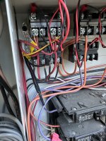
That is wired for 240 volts.
Make sure that you have 240 volts.
Check the secondary for voltage.
If the system was not working, it would give an error code.
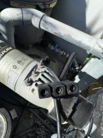
Make a better connection for testing voltage.
Make two short pieces of wire with a bare copper spot for testing.
Put the wires at the cell connection points.
The connectors are 1/4" male and female spade connectors.
Test for voltage at the two bare copper spots.
Get some meter lead alligator clips to clamp on and test voltage.


Make sure that you have 240 volts.
Check the secondary for voltage.
If the system was not working, it would give an error code.
Make a better connection for testing voltage.
Make two short pieces of wire with a bare copper spot for testing.
Put the wires at the cell connection points.
The connectors are 1/4" male and female spade connectors.
Test for voltage at the two bare copper spots.
Get some meter lead alligator clips to clamp on and test voltage.
Try the DC Voltage at the connection points again using the jumpers to ensure that you are getting a good reading.
Test the DC voltage of a battery to make sure that the meter is reading correctly.
Try a 12 volt or 9 volt battery.
If the amperage was low, it would give an error.
Get the test leads connected before the system turns on so you can watch it change.
Test the DC voltage of a battery to make sure that the meter is reading correctly.
Try a 12 volt or 9 volt battery.
If the amperage was low, it would give an error.
Get the test leads connected before the system turns on so you can watch it change.
There are 12 wires coming off of the secondary, so you need the diagram to see how to test.What’s the best way to check the Voltage on the secondary?
It looks like you have 3 Secondary Sets of Leads.
Voltage at the transformer secondary will be AC.
I am not sure, but maybe this.
______________________________________________________
Brown to (Brown/White) should be 19 volts AC.
______________________________________________________
Blue to (Blue/White) = 37.5 Volts AC.
YEL CT means Center Tap (I think).
So, from Blue to Yellow or (Blue/White) to Yellow should be 37.5/2 = 18.75 Volts AC.
______________________________________________________
Orange to (Orange/White) = 32.5 Volts AC.
From Orange to Yellow or (Orange/White) to Yellow should be 32.5/2 = 16.25 volts.
______________________________________________________
I think that the system adjusts the voltage to try to maintain a constant current by increasing or decreasing the voltage to the cell.
Last edited:

I think that this is probably correct.
You have two Secondary Windings.
_____________________________________________________________________________________________________________
The Brown to Brown/White is a separate winding.
Brown to Brown/White is 19 VAC at 2 amps and this is probably the power for the circuit board.
_____________________________________________________________________________________________________________
This winding is multitap to provide multiple voltages.
Blue to Blue/white is 37.5 Volts AC at 6 amps and this is the power for the cell.
Blue to Yellow should be 37.5/2 = 18.75 Volts AC.
Blue/White to Yellow should be 37.5/2 = 18.75 Volts AC.
Orange to orange/White is 32.5 Volts AC.
Orange to Yellow should be 32.5/2 = 16.25 volts AC.
Orange/white to Yellow should be 32.5/2 = 16.25 volts AC.
Blue to Orange = 2.5 volts AC.
Blue/White to Orange/White = 2.5 volts AC.
Blue to Orange/white = 35 volts AC.
Blue/white to orange = 35 volts AC.
Verify all voltages. Note Voltage is AC.
_________________________________________________
With all power off, check resistance and post readings from:
Brown to Brown/White = ________Ohms.
Brown to Blue = _________Ohms (Should be O.L).
Blue to orange = ________Ohms.
Blue to yellow. = ________Ohms.
Blue to orange/white = ________Ohms.
Blue to blue/white= ________Ohms.
____________________________________________________
Last edited:
KEA114UL-75V6000-PT
As you can see, the primary can be wired for 120 or 240.
The secondary should output 32.5 Volts AC or 37.5 Volts AC.
It think that the controller can select the output of the secondary depending on the current going to the cell.
I think that it chooses the voltage to keep the current more consistent.
You can check the resistance of the primary and secondary windings.
The DC voltage should be 27 volts under load.
You can check the bridge rectifiers.


kul
Bronze Supporter
- Oct 1, 2021
- 1,434
- Pool Size
- 15000
- Surface
- Plaster
- Chlorine
- Salt Water Generator
- SWG Type
- Pentair Intellichlor IC-60
My hunch is that your cell is not producing due to temperature. My cell is also not producing at this time. It usually happens when the temps get cooler. You can go through what James has noted, but if nothing turns up may also just wait a few weeks for temps to be consistently warmer and see if it starts producing again.
It would say "LO".My hunch is that your cell is not producing due to temperature.
Below 11°C (51°F), chlorine production is not permitted.
If more chlorine should be needed, activating the “Boost” mode will override this cold water feature allowing chlorine production for 24 hours of operation.
Try putting the system in Boost Mode to see if that makes any difference.
To Enter Boost Mode Press and Hold "Temperature" Button for 10 Seconds

