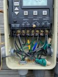
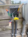
Howdy! I'm opening the pool today, and along with that is upgrading the existing mechanical timer to the P1353 digital timer. The advantage of this is I will now be able to program it for both high and low speeds on my pump, which is currently controlled manually by a SPDT switch near the timer box.
I figured I'd run the plan by the brains on this forum, just to make sure I'm doing it right (I know, I know, hire an electrician, etc).
1. Document the high and low wires running from the pump to the SPDT switch.
2. Document, disconnect and remove the mechanical timer from the timer box.
3. Run two new wires from the timer box to the current switch box, which will become a junction box.
4. Wire nut the exiting wires from the timer box to the switch box to the line wires running from the switch box to the pump.
5. Wire nut the two new wires from the timer box to the high and low wires in the switch box.
6. Connect the existing line wires and the new high/low load wires to the appropriate terminals on the new timer.
7. Setup the timer for "Mode 2", which controls a 2-speed pump + aux.
My pump is a 230V Hayward Super II pump with a 2 HP motor. The wiring diagram on the motor is below. I plan to connect the heater and SWG to the 3rd/AUX circuit on the timer.

Is it as simple as that? I will add that I'm fairly competent at electrical work, so this doesn't feel out of my wheelhouse.
TIA!
I figured I'd run the plan by the brains on this forum, just to make sure I'm doing it right (I know, I know, hire an electrician, etc).
1. Document the high and low wires running from the pump to the SPDT switch.
2. Document, disconnect and remove the mechanical timer from the timer box.
3. Run two new wires from the timer box to the current switch box, which will become a junction box.
4. Wire nut the exiting wires from the timer box to the switch box to the line wires running from the switch box to the pump.
5. Wire nut the two new wires from the timer box to the high and low wires in the switch box.
6. Connect the existing line wires and the new high/low load wires to the appropriate terminals on the new timer.
7. Setup the timer for "Mode 2", which controls a 2-speed pump + aux.
My pump is a 230V Hayward Super II pump with a 2 HP motor. The wiring diagram on the motor is below. I plan to connect the heater and SWG to the 3rd/AUX circuit on the timer.

Is it as simple as that? I will add that I'm fairly competent at electrical work, so this doesn't feel out of my wheelhouse.
TIA!


