Intermatic P1353 Wiring

May 11, 2015
38
Bridgewater, NJ
Howdy! I'm opening the pool today, and along with that is upgrading the existing mechanical timer to the P1353 digital timer. The advantage of this is I will now be able to program it for both high and low speeds on my pump, which is currently controlled manually by a SPDT switch near the timer box.

I figured I'd run the plan by the brains on this forum, just to make sure I'm doing it right (I know, I know, hire an electrician, etc).

1. Document the high and low wires running from the pump to the SPDT switch.
2. Document, disconnect and remove the mechanical timer from the timer box.
3. Run two new wires from the timer box to the current switch box, which will become a junction box.
4. Wire nut the exiting wires from the timer box to the switch box to the line wires running from the switch box to the pump.
5. Wire nut the two new wires from the timer box to the high and low wires in the switch box.
6. Connect the existing line wires and the new high/low load wires to the appropriate terminals on the new timer.
7. Setup the timer for "Mode 2", which controls a 2-speed pump + aux.

My pump is a 230V Hayward Super II pump with a 2 HP motor. The wiring diagram on the motor is below. I plan to connect the heater and SWG to the 3rd/AUX circuit on the timer.
774F4929-72D2-479A-A3D2-74578FE1C4AE.jpg
Is it as simple as that? I will add that I'm fairly competent at electrical work, so this doesn't feel out of my wheelhouse.

TIA!
 
You may already be knee-deep into this project, or perhaps even have it done by now. What you are explaining seems reasonable as best as I can visualize. Of course you can always post a pic of what you have there so we can see everything that will be joined together. If this reply is too late and you're already done........ cheers. :cheers:
 
  • Like
Reactions: chrismar
I was knee deep!

I got 90% of the way there. Turns out my pump needed mode 7. High speed works fine, low speed is acting strange. It makes a crazy sound and eventually the overload protection kicks in and the motor turns off.

I’ll need to do some more trouble shooting tomorrow as I ran out of daylight. :(
 
Ok, I'm officially stumped, any help would be appreciated. I can't get mode 2 to work, so I'm running with mode 7. Pump wiring label is up in the first post. Everything is 240V.

Here's my diagram of how it's all connected right now:
diagram.jpeg
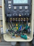
Here's the connections on the timer:
timer.jpeg
Terminal 1: Leg A from the breaker and a jumper to terminal 7
Terminal 2: Leg B from the breaker, 1 leg of the SWG and heater and a jumper to terminal 3
Terminal 3: Jumper from terminal 2 and jumper to terminal 5
Terminal 4: "high speed" load wire to the J-Box and wire-nutted to the wire attached to terminal 2 on the motor
Terminal 5: Jumper from terminal 3
Terminal 6: "low speed" load wire to the J-Box and wire-nutted to the wire attached to terminal 3/4 on the motor
Terminal 7: Jumper from terminal 1
Terminal 8: "common" wire to the J-Box and wire-nutted to the wire attached to terminal 1 on the motor

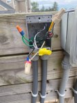
Here's the J-Box:
j-box.jpeg
Top 2 wires (brown wire nut): "high load" (yellow tape wire) from timer terminal 4, "high" (red tape wire) connected to terminal 2 on the motor
Middle 2 wires (yellow wire nut): "common" running from timer terminal 8, "common" (white tape wire) connected to terminal 1 on the motor
Bottom 2 wires (brow/red wire nut): "low load" (blue tape wire) from timer terminal 6, "low" (white wire) connected to terminal 3/4 on the motor

And the motor:
pump.jpeg
Top: white taped wire from the j-box to terminal 1 on the motor (common)
Middle: red taped wire from the j-box to terminal 2 on the motor (high speed)
Bottom: white wire from the j-box to terminal 3/4 on the motor (low speed)

High speed seems to kick on just fine when pressing the "circuit 1" on/off button.
Low speed makes a strange noise, and if I let it run some protection kicks in and the motor shuts off

Thanks again for any insight!
 
For S&Gs I tried swapping terminals 4 and 6 (high and low loads) to see if low would work when connected to the “known good” high terminal. It did, once. On the second attempt it started making its weird noise again. And then I tried “circuit 2” for low (which now had the high load connected) and now it’s making the odd sound.

After this I moved everything back to its proper spot and now both high and low don’t work and are making the strange sound.

Defeated. ?
 
Seems the new timer is borked. I went out again and tied the common line from the pump motor directly to one of the breaker legs, then took the high line and tied it to the other leg. Viola! High speed primed up just fine! Disconnected the high line from the breaker and connected the low line and that kicked right on too!

Long story short, ended up reinstalling the old single speed mechanical timer and not the manual SPDT switch and just wired it for high speed full time.

I’ll try again when I get a replacement timer.
 
Please let us know how it works and what they say if they tell you what is wrong with the current one?
I think you're the first infant mortality of a 1353 I've heard about. I'm sure it happens once in a while, but thankfully it's rare.
 
  • Like
Reactions: chrismar
Thread Status
Hello , This thread has been inactive for over 60 days. New postings here are unlikely to be seen or responded to by other members. For better visibility, consider Starting A New Thread.