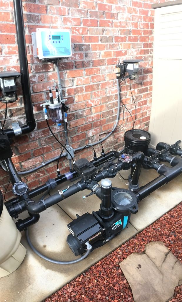
IntelliChem Setup

For a flow switch, polarity doesn’t matter. It’s simply closing the circuit between the black and red wires.

Is that how Pentair says to plumb the supply and return piping into the flow cell :scratch: What’s that thing between the supply and return ports, a check valve?? I don’t think there’s enough of a pressure differential across that pipe to get any flow. I would take the supply side tube and hook it up to the discharge port on the pumps wet end (there’s a 1/4” plug there) as that would be the point of maximum pressure and then the return tube would be plumbed somewhere after your equipment and just before the water goes below ground to the pool.
 
That isn't enough flow and now you see why people plumb the return side of the flow switch to the suction side of the plumbing. You want to create as large of pressure differential between the inlet and outlet as possible so that you can run your pump at the lowest speed possible. Leaving plumbed the way you have it now you will probably not get adequate flow until 2500-2800 rpm on the pump.

The flow switch wiring should be interchangeable so that isn't the issue either.

Dang, I was afraid of that. Guess that's what I get for listening to the manufacturer. This is what they told me when I asked them about doing that: "You do not want to put anything on the suction line because then you are pulling water through the flow cell and can damage the flow switch."

Actually, when I ramp up the pump to higher speeds the flow gets worse. Probably because the pressure downstream of the check valve is closer to the upstream pressure, so overall less differential.

For a flow switch, polarity doesn’t matter. It’s simply closing the circuit between the black and red wires.

Is that how Pentair says to plumb the supply and return piping into the flow cell :scratch: What’s that thing between the supply and return ports, a check valve?? I don’t think there’s enough of a pressure differential across that pipe to get any flow. I would take the supply side tube and hook it up to the discharge port on the pumps wet end (there’s a 1/4” plug there) as that would be the point of maximum pressure and then the return tube would be plumbed somewhere after your equipment and just before the water goes below ground to the pool.

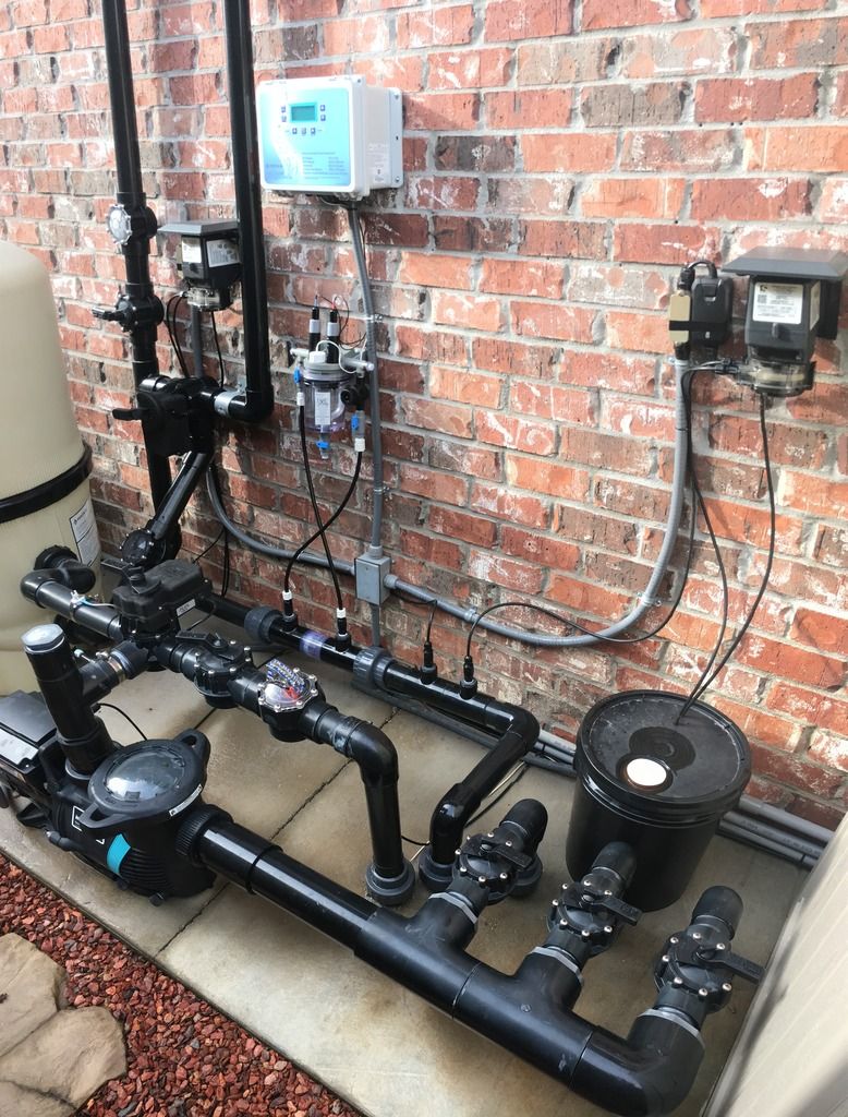
Thanks for clearing up the flow switch wiring question! Makes sense.

Pentair did not want to give advice on how to plumb it (other than what they show in the manual, which shows the inlet before a heater and the outlet after the heater (because EVERYONE has a heater, right?) ) because "they are not installers". Yes, it is a check valve in between the two injection quills. I thought/hoped it would give me the differential I needed, but apparently not.

Yes, I do have an unused 1/4" tap already right after the pump discharge. I would need to drill it out a bit for the 3/8" tubing, but it's simple. Hopefully that will give me enough differential. My filter consistently shows 6 psig on the gauge. I would probably start by just leaving the outlet where it is (downstream of the check valve), as there really isn't much more down stream before going under ground to drop the pressure.


A lot of people have had success using the bung on the bottom of the pump basket for the return line

Oi, bung....it’s a threaded plug....p_l_u_g ...

And there should be two - one at the bottom of the strainer basket which is the suction side and one at the bottom of the volute which is the pressure/discharge side. If you want to “push” water thru the cell then use the PLUG at the bottom of the volute...

- - - Updated - - -

They’re typically 1/4” NPT so you can probably find an NPT to compression adapter for your tube size.

Ok. Thinking this on the volute plug or this on the existing tap I have right off the pump discharge. Either one should give me right at about the same pressure going into the flow cell. Coming off the existing tap though may be more "out of the way", since my volute plug is on the side of the pump closest to the stepping stones.
 
Oi, bung....it’s a threaded plug....p_l_u_g ...

And there should be two - one at the bottom of the strainer basket which is the suction side and one at the bottom of the volute which is the pressure/discharge side. If you want to “push” water thru the cell then use the PLUG at the bottom of the volute...

- - - Updated - - -

They’re typically 1/4” NPT so you can probably find an NPT to compression adapter for your tube size.

What if I said threaded bung?

What do you call the hole a bung goes in?
 
Ok. Thinking this on the volute plug or this on the existing tap I have right off the pump discharge. Either one should give me right at about the same pressure going into the flow cell. Coming off the existing tap though may be more "out of the way", since my volute plug is on the side of the pump closest to the stepping stones.

I would say whatever is easiest for you. If the pump plug is in an awkward or easily damaged spot, then the discharge plug will be fine. Pressure should be very good on the side before the filter.

What do you call the hole a bung goes in?

Threaded port ....
 
Ok, well it dawned on me this morning (sorry for the pun) what the REAL problem was: the injection quills that I am using on either side of the 2" check valve are actually injection quills with built-in check valves. :brickwall:

I don't know how this didn't occur to me sooner (like when I unscrewed the tubing on the inlet side and very little water was coming out :scratch:), but once I removed the little duckbills in each one...magic! Good flow now, so no need to re-route tubing. This of course means that the 2" in-line check valve does create enough of a differential as I hoped.

However, now I have a new issue. When I run the pump on low/normal speed (1700 rpm), all is well, but when I bump it up above 2000 rpm the flow cell starts leaking where the probes screw in (as shown here). The o-rings are there and I even tried putting some petroleum jelly on them, but either way they just can't seem to hold a seal above 2000 rpm. Anyone else have this problem and know the solution?
 

Enjoying this content?

Support TFP with a donation.

Give Support
No, no, no and heck no!!!! No petroleum jelly on o-rings!!! Silicone lube only and preferably one that DOES NOT have Teflon in it. Petrolatum will degrade rubber.

I agree with Brian, try some tape on the threads and give it a little snug past hand tight. Try adding back the duck-bill check valve in the return tube.

- - - Updated - - -

Manual says not to and they're not tapered threads. Guess it can't hurt to try though.

Straight pipe threads (typically called “G” threads) SUCK! You’re going to need tape.
 
No, no, no and heck no!!!! No petroleum jelly on o-rings!!! Silicone lube only and preferably one that DOES NOT have Teflon in it. Petrolatum will degrade rubber.

I agree with Brian, try some tape on the threads and give it a little snug past hand tight. Try adding back the duck-bill check valve in the return tube.

Ok. I'll clean off the petro jelly and use the Teflon tape (no silicone lube handy). Why do you suggest adding the duckbill back on the return line?
 
Duck bill will add backpressure and slow down the flow a bit....maybe that might help with the leak :scratch: just spitballing ideas....
 
Gotcha. Well, the Teflon tape and silicone lube (I actually found some I didn't remember I had) seemed to do the trick. BTW, the treads on the probes ARE actually tapered, which is weird...not used to seeing tapered threads on an o-ring joint. The threads on the flow sensor though are not threaded, so I put some lube on that o-ring as well because I think that one may have been leaking as well. Anyway, all is good now. No leaks even at 3500 rpm. Thanks guys!
 
You can put a tapered threads (NPT) plug into a straight thread port (with a healthy amount of tape and Teflon paste, but not the other way around. Normally mated NPT threads don’t need an o-ring as the threads are the sealing surface. Their design might incorporate different thread types which is poor engineering but probably sufficient for a consumer product.

If this were an industrial setting and I saw that, I’d rip the engineer who designed that a new one.....

Agreed!
 
Hey Matchless good to see you got everything worked out! As I'm looking to go the same route can you tell me what check valve you used and what fittings you needed to get the flow sensor plumbed-in.
 
Hey Matchless good to see you got everything worked out! As I'm looking to go the same route can you tell me what check valve you used and what fittings you needed to get the flow sensor plumbed-in.

I actually used a Del Ozone check valve only because I needed one with the same take-out dimension as what was there before (when I was using the Ozone) between the two unions. Here's a link, but any check valve would probably work the same: https://www.amazon.com/gp/product/B006WVWWG6/ref=oh_aui_detailpage_o05_s00?ie=UTF8&psc=1

Other parts I used are linked as follows:

3/8" Injection Check Valve (don't forget to remove the duckbill on at least the one being used for the inlet line...I removed them on both the inlet and outlet lines)

2" x 2" x 1/2" Tees (except since I have black piping I had to use a 2" x 2" x 1" tee with a 1" x 1/2" bushing)

2" Unions (because I use unions probably more than I should, but so far they've come in very handy and no leaks (knock on wood))

Plenty of Teflon tape and just a bit of silicone grease (for the o-rings, thanks to Matt for the tip there!).

Good luck! Hope this helps.
 

Enjoying this content?

Support TFP with a donation.

Give Support
Thread Status
Hello , This thread has been inactive for over 60 days. New postings here are unlikely to be seen or responded to by other members. For better visibility, consider Starting A New Thread.