IC60 & IntelliPH no longer working (5 months old) - Input?
- Thread starter tomas21
- Start date
You are using an out of date browser. It may not display this or other websites correctly.
You should upgrade or use an alternative browser.
You should upgrade or use an alternative browser.
This is an EXCELLENT explanation!! Bravo sir! This should be posted in the Iph info page! @MyAZPoolThis is what I've come up with to illustrate the fix (to the over-current problem). Basically the same as @ogdento's, just a different approach. There are three variations. The splices could be soldered (my preference) or crimped or even wire-nutted, or achieved in some other way (@ogdento suggested using a terminal block to make the connections). If soldered, I'm picturing some sort of epoxy or even hot glue to seal up and insulate the connection. In the variations that use a jumper wire, I'm showing the jumper wire wrapping around the thicker two wires, and then all that would get soldered. You could use that MO for the variation that doesn't have a jumper, too. Where the wires pass through the splice, I would just shave the insulation off the wires without cutting the wire itself. That's the way I'd do it, but there are plenty of other ways to make that connection. The trick is to make a good mechanical and electrical connection that would ward off any corrosion (which is why I like to solder).
This first variation could be used when the connector hasn't yet melted. A pro-active preventative measure. Something like this is all Pentair would have to do to solve for this issue.
View attachment 421750
Variation #2 would be used for a fried connector, assuming the burn wasn't too severe. Though some of the IC60 melt downs are pretty bad.
View attachment 421751
Variation #3 is a hybrid, which could be used whether the connector was burned or not, again, assuming the burn wasn't too severe. This is what I would do if I had it to do over again. Instead, I removed the connector and soldered the large wires directly onto the board. That's a viable fix if you can pull off the soldering, but this way would be easier with less chance of messing up the board. I'm going to go back in and connect the reds and blacks as shown, just to alleviate all that current flowing through the traces of my board. Perhaps all that current through the traces is a contributing factor to those other COM components burning up?
View attachment 421752
Just want to point out that this has yet to be tried by anyone (that I know of): splicing the reds and blacks together before the connector, that is. This is our best guess of a fix. You could be first!
Removing the burned connector and soldering the eight wires directly to the board does work, I can confirm that, as that solved my IntelllipH failure, and has been working for several months now.
Wow @Dirk you got it... those illustrations are exactly what I was trying to convey. Awesome job on them, and quite professional looking I might add *cough*. I agree that #1 should handle most cases since the current going through the connector will be pretty low.
At the moment I don't think high currents on the red/black is a contributing factor to the comm parts burning up, but the jury is still out on why that's happening. The op, @tomas21, and Turbo1Ton had no blown comm parts but the connector burned at the red (and black) wires.Perhaps all that current through the traces is a contributing factor to those other COM components burning up?
For the red/black wires to kill the comm parts, a lot of current - supplied by the red wire - would have to find a path through the comm components. But the comm port is powered by it's own regulated supply that didn't blow up, and the protection diodes go to ground... so there shouldn't be any current flowing in them unless there's a spike on the data lines or maybe one of the data lines shorted to Vds (red wire) somewhere.
Hey @tomas21 and @Zaffor... if either of you have a multimeter, could you see if there's any continuity between either the white or green wire and the red? (it's probably easiest to check it on the connector pins... just use the green/white pins that go to the relay, not coming in from outside the box)
- Nov 12, 2017
- 12,638
- Pool Size
- 12300
- Surface
- Plaster
- Chlorine
- Salt Water Generator
- SWG Type
- Pentair Intellichlor IC-40
Thanks guys. This issue is becoming so common that I thought an illustration was needed so we could all see what we are talking about. I'm looking forward to the first of us that will try one of the mods!
Flying Tivo
TFP Guide
- Jan 24, 2017
- 3,100
- Pool Size
- 7500
- Surface
- Plaster
- Chlorine
- Salt Water Generator
- SWG Type
- Pentair Intellichlor IC-40
- Nov 12, 2017
- 12,638
- Pool Size
- 12300
- Surface
- Plaster
- Chlorine
- Salt Water Generator
- SWG Type
- Pentair Intellichlor IC-40
OK, great, that's what I was asking about (the "electrons"). Even though the reds and blacks are connected in two, parallel places, the current won't get split between them both, the bulk of the current will go through the splice, and only the current needed for the board will go through the connector. Which is what we want.I agree that #1 should handle most cases since the current going through the connector will be pretty low.
I'm not sure what to suggest when the connector is completely demolished, short of the fix I used, soldering the wires directly to the board. I should point out an issue I had with that fix that I didn't describe in my write up.
After struggling with the soldering, and finally getting it done, I couldn't reassemble everything into the IpH box! Argh!! Because I had cut out the connector, and soldered to the board, that eliminated just enough length so that one set of the wires (red, black, green, white) could no longer reach between the board and where they come into the IpH box! So I had to cut those four and splice in some extensions. Fun times. But had I realized that earlier, and what we now know, I would have fixed it differently, and perhaps this is the fix for a completely destroyed connector:
1. Label or otherwise record where all eight wires go, in terms of which holes they lead to on the circuit board.
2. Cut all eight wires.
3. Cut off the fried connector. (I used a Dremel for this.)
4. Connect the two reds together including a third, smaller jumper wire.
5. Connect the two blacks together including a third, smaller jumper wire.
6. Splice smaller wires onto each of the two greens and two whites.
7. Solder all six jumper wires to the board.
Using the smaller jumpers will solve for the reach problem. It'll also greatly ease the job of soldering to the board. I had originally tried to solder to the pins that were left after cutting off the connector, but the wires were so big that the heat of the soldering melted the solder that connected the pins to the board. Perhaps with a smaller gauge wire, that could better be done that way. But if the pins have to be desoldered, the smaller gauge wire will be much easier to solder to the holes in the board.
That's assuming, @ogdento, that the COM wires can be reduced in size like that. I'm thinking they aren't carrying any sort of large current. I'm guessing the COM wires (green and white) are fat like that only because the red and black wires needed to be, and that's how the cable is manufactured.
Flying Tivo
TFP Guide
- Jan 24, 2017
- 3,100
- Pool Size
- 7500
- Surface
- Plaster
- Chlorine
- Salt Water Generator
- SWG Type
- Pentair Intellichlor IC-40
Electrons as well as H2O will always follow the path of least resistance. You make a great point in soldering, which assures this path.he current won't get split between them both,
- Nov 12, 2017
- 12,638
- Pool Size
- 12300
- Surface
- Plaster
- Chlorine
- Salt Water Generator
- SWG Type
- Pentair Intellichlor IC-40
Exactly. As impressive looking as @Zaffor's terminal box is (back in post #40), personally, I would have soldered all those connections. Depends on your climate, I suppose, and how often you anticipate having to undo those connections, but I just trust solder.You make a great point in soldering, which assures this path.
I doubled the task of assembling my low voltage garden light wiring by soldering every connection, and then using the goopy wire nuts over that. Seven years, no shorts or dead lights. Just trying to find a corroded connection under years of growth and mulch and dead leaves could take more effort than the initial soldering. I did the same for my irrigation box wiring.
Troubleshooting corrosion can be a nightmare, and it can cause all sorts of problems (like a melted IpH connector), including intermittent problems, which are the worst. And the pool equipment pad environment might be one of the harshest a residential home has to offer: water, salt, acid fumes, UV, hot, cold, high voltage, low voltage. It's got it all.
No offense, Zaffor, your junction box is a thing of beauty. But so is a smooth, shiny solder joint! You can see yourself!!
Last edited:
- Nov 12, 2017
- 12,638
- Pool Size
- 12300
- Surface
- Plaster
- Chlorine
- Salt Water Generator
- SWG Type
- Pentair Intellichlor IC-40
Thanks Felipe. If we ever get to the end of this adventure, we probably should assemble everything into one thread: your fix, my winter switch mod, the IntellipH mod, the surge board stuff. All in one place...Great Work @Dirk on the drawings!
Flying Tivo
TFP Guide
- Jan 24, 2017
- 3,100
- Pool Size
- 7500
- Surface
- Plaster
- Chlorine
- Salt Water Generator
- SWG Type
- Pentair Intellichlor IC-40
Some people think that something that is worth doing, then its worth doing Twice! 

- Nov 12, 2017
- 12,638
- Pool Size
- 12300
- Surface
- Plaster
- Chlorine
- Salt Water Generator
- SWG Type
- Pentair Intellichlor IC-40
Well that hits home. I'm in the middle of redoing some outdoor stairs. It's taken me a month! Should'a done it right the first time...Some people think that something that is worth doing, then its worth doing Twice!
I love soldering connections! I did this to make swapping out a bad valve easier. I wasnt sure what the longevity is on these intellivalves. The terminal block also sits inside a sealed jbox. All wires were crimped with ferrules as well which should further shield them. I am not even sure corrosion caused that melted wire issue. The iph was swapped out and probably 6-8 months old when it gave out.Exactly. As impressive looking as @Zaffor's terminal box is (back in post #40), personally, I would have soldered all those connections. Depends on your climate, I suppose, and how often you anticipate having to undo those connections, but I just trust solder.
I doubled the task of assembling my low voltage garden light wiring by soldering every connection, and then using the goopy wire nuts over that. Seven years, no shorts or dead lights. Just trying to find a corroded connection under years of growth and mulch and dead leaves could take more effort than the initial soldering. I did the same for my irrigation box wiring.
Troubleshooting corrosion can be a nightmare, and it can cause all sorts of problems (like a melted IpH connector), including intermittent problems, which are the worst. And the pool equipment pad environment might be one of the worst a residential home has to offer: water, salt, acid fumes, UV, hot, cold, high voltage, low voltage. It's got it all.
No offense, Zaffor, your junction box is a thing of beauty. But so is a smooth, shiny solder joint! You can see yourself!!
- Nov 12, 2017
- 12,638
- Pool Size
- 12300
- Surface
- Plaster
- Chlorine
- Salt Water Generator
- SWG Type
- Pentair Intellichlor IC-40
That's our working theory (or maybe just mine!). I think the conductors (male and female) are of poor quality and/or fit'n'finish, and don't connect to each other all that well. Add some dust or some damp air and corrosion sets in, which increases the resistance of the connection, which then causes heat, and probably more corrosion until the resistance and heat overwhelms the conductors and the surrounding connector. That's my story and I'm stickin' to it!I am not even sure corrosion caused that melted wire issue.
I noticed the ferrules and appreciate the good work and the time and effort involved. All neatly arranged and wire-zipped. A quality job, for sure.
- Nov 12, 2017
- 12,638
- Pool Size
- 12300
- Surface
- Plaster
- Chlorine
- Salt Water Generator
- SWG Type
- Pentair Intellichlor IC-40
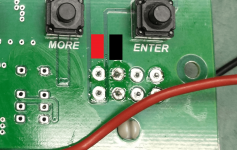
Well that's clear enough. Shoot, I had found the black but for some reason I couldn't spot that trace for the red. I may have messed up the coating by the time I went looking for it, with all my soldering attempts...oh here's a pic showing how the reds and blacks are connected together on the board (pardon the extra flux, i was trying to desolder the connector)
View attachment 421847
@ogdento can you explain where to test for continuity? I unplugged the iph for now and just plugged the cell directly into the port I wired to my jbox. I can easily replace to run some tests. I can test inside the intellicenter low voltage compartment right on the surge card also.At the moment I don't think high currents on the red/black is a contributing factor to the comm parts burning up, but the jury is still out on why that's happening. The op, @tomas21, and Turbo1Ton had no blown comm parts but the connector burned at the red (and black) wires.
For the red/black wires to kill the comm parts, a lot of current - supplied by the red wire - would have to find a path through the comm components. But the comm port is powered by it's own regulated supply that didn't blow up, and the protection diodes go to ground... so there shouldn't be any current flowing in them unless there's a spike on the data lines or maybe one of the data lines shorted to Vds (red wire) somewhere.
Hey @tomas21 and @Zaffor... if either of you have a multimeter, could you see if there's any continuity between either the white or green wire and the red? (it's probably easiest to check it on the connector pins... just use the green/white pins that go to the relay, not coming in from outside the box)
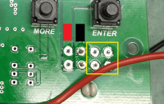
hey @Zaffor, refer to the photo below...
with the iph disconnected, I want to know if either of the 2 pins that connect to the pc board trace with the red marking (this is Vdc, the supply voltage) have continuity to any of the 4 pins surrounded by the yellow box (these are the data lines, 2 white, 2 green).

Set your meter to continuity... then put one meter probe on one of the red pins (they're both the same), and touch the other probe to each of the pins in the yellow box... see if you get a beep. then do the same with the 2 pins that connect to the trace with the black marking.
with the iph disconnected, I want to know if either of the 2 pins that connect to the pc board trace with the red marking (this is Vdc, the supply voltage) have continuity to any of the 4 pins surrounded by the yellow box (these are the data lines, 2 white, 2 green).

Set your meter to continuity... then put one meter probe on one of the red pins (they're both the same), and touch the other probe to each of the pins in the yellow box... see if you get a beep. then do the same with the 2 pins that connect to the trace with the black marking.
Got it! Im comfortable using the meter just wasnt sure where to probe. Let me pull the faceplate off to get to the boardhey @Zaffor, refer to the photo below...
with the iph disconnected, I want to know if either of the 2 pins that connect to the pc board trace with the red marking (this is Vdc, the supply voltage) have continuity to any of the 4 pins surrounded by the yellow box (these are the data lines, 2 white, 2 green).
View attachment 421915
Set your meter to continuity... then put one meter probe on one of the red pins (they're both the same), and touch the other probe to each of the pins in the yellow box... see if you get a beep. then do the same with the 2 pins that connect to the trace with the black marking.
oh and you can do it from the visible side of the board too... but the pins will be mirrored  and might be harder to get to
Thread Status
Hello , This thread has been inactive for over 60 days. New postings here are unlikely to be seen or responded to by other members. For better visibility, consider Starting A New Thread.


