- Jan 24, 2020
- 231
- Pool Size
- 29000
- Surface
- Plaster
- Chlorine
- Salt Water Generator
- SWG Type
- Pentair Intellichlor IC-60


Yah, that means the IC is drawing current through the IpH 42 minutes out of every hour, for nine hours straight. The theory is that maybe this wouldn't happen if the IpH board had the opportunity to cool down more between IC runs. I'm not sure of that. I'm stickin' with my theory that crummy conductor materials are encouraging corrosion and/or arcing. Academic, except we were exploring why this happens to some, and not others, and why it might be fine for years and then fail (that was mine). That's why I think it's corrosion. Something that happens only under certain conditions, and might take a little or a lot of time to develop.IC60 is set at 70% 7a - 4p
 www.troublefreepool.com
www.troublefreepool.com
www.troublefreepool.com
Yes that sounds right to me! It's almost like you want to crimp the two red wires together before letting them go into the connector on the board (and do the same with the black wires)OK, thanks, that's clear. So the way to mod an un-fried IntellipH is to leave the connector alone. That solves for the COMM bus, as the white and green wires will be left in place. Then to connect the two reds together, and then the two black togethers, before the connector in whatever way is handiest (terminal block, cut and solder, even wire nuts, whatever). I'm thinking you could also leave the blacks and reds in the connector alone, too. That would supply the power the board needs. Just splicing the reds together and the blacks together is all you'd have to do. @ogdento, does that sound right?
my head hurts@ogdento, out of curiosity, from an electron perspective so to speak, if the two reds are touching with sufficient contact, and the two black are touching, before the connector, but they're both still wired to the connector and ultimately touching again, via the traces on the board, does the flow of current (all the electrons) get split equally between those four touch points, or is the current that would flow through the connector and the traces on the board only what the board is drawing, and the current that flows through the other touch points (the ones before the connector) carry all the current that the IntellliChlor is drawing. See what I'm getting at?
and there's a bit at play here, but if I'm understanding what you're describing... the first point where the reds are crimped/connected/soldered would act like a zero-ohm resistor or a "short" (let's call it R-short) that is in parallel with the second point that - for simplicity - includes the poorly-mated-connector-halves and the pc board trace, which would act like a low-ohm resistor (let's call it R-connector). In that case, since R-short and R-connector are in parallel, R-short prevents any voltage drop across R-connector... so no current can flow through R-connector. Of course, depending on where you connected the jumper wire to power the board there could be some current through some part of R-connector, but it would only be as much as the board draws. I think??I'd do almost exactly what you described in quote #1 (leave the connector alone, leave the white/green wires untouched)... but it depends on the condition of the red/black terminals on the connector... if at least one of each is still decent enough to power the board, I'd:To fix a fried connector, you'd cut off the connector, after making note of which green wires and white wires go to which pins, connect the reds, and the blacks, each with a third wire, that would connect to the corresponding pins on the board. You'd still be left with soldering the greens and the whites to the board. That's the tough part.
correct - the comm wires connected the board are interrupted - connected or disconnected - by the relay.Also, @ogdento, just so I'm clear, the COMM connections on the IntellipH don't work like connecting COMM wires elsewhere, like to an EasyTouch or ScreenLogic or an Indoor Controller, where you just connect together all the wires of the same color. The IntellipH board actually disconnects (interrupts) the COMM wires running through it. Do I have that right?
Mark it down son... It's your first but not your last.Pentair tech's state... In the x amount of years I have worked here I have never had a claim related to the IntelliPH and a burnt connector... come on.. : )
www.troublefreepool.com


Thank you for the walk through on all my ponderings!!my head hurts


 www.troublefreepool.com
That's ridiculous, there are even comments about it on Pentair's own IntellipH page, in its Questions section! Pentair acknowledged the comments, with a generic answer, but that means somebody over there read 'em...Pentair tech's state... In the x amount of years I have worked here I have never had a claim related to the IntelliPH and a burnt connector... come on.. : )
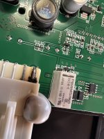
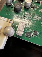
Man @Zaffor sorry to see it. Yours is another one where the comm circuitry is fried, as well as the red/black leads to the connector. The comm line looks to have had some kind of surge event because the relay blew and all the protection diodes (thyristors) are dead, and I'd bet the comm chip is dead... but why are the red wires on your connector also burned up?!