I went from a Intermatic T 104? R outdoor timer to this suraielec digital. I have no electrical training and I took old intermatic off and forgot to take a picture of the wiring before removing. No electricians available to come for weeks and my inground pool will be dark green soup. I am in a pickle. I mounted the suraielec box and pulled the wires into the box. I have a salt system on the right. On the left is the switch box for light and pool vac pump system. The bottom right is from the breaker box on outside of house. The bottom left is the pool pump. I am unsure if I should pigtail some of the wiring or will the suraielec be able to hold all of the 3 loads. Here are the pictures below of what I have at the present time.

I Have a new Suraielec digital timer swith model UBTD01A/T I can't wire need help
- Thread starter sluk
- Start date
You are using an out of date browser. It may not display this or other websites correctly.
You should upgrade or use an alternative browser.
You should upgrade or use an alternative browser.


Are you combining 120V and 240V loads? White wires indicate the neutral of a 120V system (120V SWG?). A booster pump should be on its own timer, not a switch coming from a single timer. Is there a GFCI in the light circuit or at the main circuit-breaker panel? Much more information is needed.
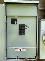
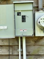
Yes I believe that there is a combination of 120 and 240. The picture of the gray switch box picture #4 controls the pool light and the booster pump so they can be turned on and off independently and enter the timer box on the left. Main breaker panel wiring is coming in from house into box at bottom right with red, white, black and copper wires. We have always had light and booster on one timer. There is a GFCI under the switches for booster and light pic #4 little gray box below the 2 red swicthes. The pictures below this post are of the outside power breaker box. The #4 picture is in the above 1st post.
Attachments
Last edited:
You really need to identify which wires are for the pump(s)/SWG and which is the light. Most likely the black wire in the rigid conduit is for the light, but you have to look in the breaker panel to be sure.Yes I believe that there is a combination of 120 and 240. The picture of the gray switch box picture #4 controls the pool light and the booster pump so they can be turned on and off independently and enter the timer box on the left. Main breaker panel wiring is coming in from house into box at bottom right with red, white, black and copper wires. We have always had light and booster on one timer. There is a GFCI under the switches for booster and light pic #4 little gray box below the 2 red swicthes. The pictures below this post are of the outside power breaker box. The #4 picture is in the above 1st post.
two red for pool pump with green bottom left and 2 red for booster with green side left. one black and one white for light on side left. red black and white main power from house bottom right.

Last edited:
Thread Status
Hello , This thread has been inactive for over 60 days. New postings here are unlikely to be seen or responded to by other members. For better visibility, consider Starting A New Thread.