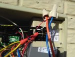
Hi all. I have an Easy Touch 4 panel (single body) and needed control over 3 valves (one for diverting water from returns to water features, one for tanning deck bubblers, and one for deck jets). The Easy Touch 4 Single Body panel can only control 2 valves (A & B).
I ended up finding some threads here regarding this and just thought I'd write a HOWTO on a nice self-contained SPDT I found on Amazon and getting it to work with the actuator.
You will need a free relay port (AUX1-AUX3 if EasyTouch 4, AUX1-AUX7 if EasyTouch 8), although you don't actually use the relay itself.
I bought this:
Functional Devices RIB2401B. https://www.amazon.com/gp/product/B000LEUJU6
It is a nice self-contained SPDT that works with 24VDC which is what the AUX port puts out from the board. Plus a single one fits nicely in the low voltage area under the fuses.
Here's what you need to do to get it hooked up:
1) Find a free AUX port and connect the left black wire on the relay to the YELLOW/WHITE (Common) wire on the RIB2401B. Connect the right black wire on the relay to the BLUE/WHITE (24VDC) wire on the RIB2401B. I ended up just keeping them hooked up to the relay (you don't use the relay outputs), but you can also cut the wires and splice them together.
2) Cut the end of the pentair valve actuator off. You will see a BLACK, WHITE, and RED wire.
3) Find the wire bundle connecting the fuses in the upper right of the panel to the board. You're going to need to cut two of the wires and splice into them. You will be cutting the RED wire and the RED/WHITE wire.
4) Splice the BLACK wire from the valve actuator to the RED wire coming from the fuse box. Also be sure to wire splice the RED wire back to the control panel as well.
5) Splice the YELLOW wire coming from the RIB2401B to the RED/WHITE wire coming from the fuse box. Also be sure to wire splice the RED/WHITE back to the control panel as well.
6) Splice the RED wire coming from the valve actuator to the BLUE wire coming from the RIB2401B
7) Splice the WHITE wire coming from the valve actuator to the ORANGE wire coming from the RIB2401B
You're done!
Now when you turn on the AUX relay, it will cause the SPDT to feed 24VAC to the actuator one way, and when you turn it off, it will feed 24VAC to the actuator the other way. You may need to switch the actuator switch to get it turning the correct way when you enable/disable the AUX relay.
Hope this helps!


