Help with closing pool waterfall

Fedorafan

Active member
Jun 21, 2022
41
Olivette, MO
Hi everyone,

This year, I’m planning to close my pool myself for the first time, but I’m unsure about how to properly handle the waterfall. As shown in the first photo, the water for the waterfall flows through a long strip, and the waterfall has its own dedicated pump, as seen in the second photo.

My current plan is to blow out the water from the pump housing, but I’m unclear on the next steps. Specifically, I’m wondering how to add antifreeze to the system and whether I should seal the strip (when I opened the pool, there was no seal around the strip). Should I blow out the water first and then add antifreeze through the pump, or is there a particular method I should follow for closing the waterfall feature?

Any advice or step-by-step instructions would be greatly appreciated! Thanks in advance.
 

Attachments

  • Screenshot 2024-09-22 at 12.53.15 PM.png
    Screenshot 2024-09-22 at 12.53.15 PM.png
    914.9 KB · Views: 17
  • Screenshot 2024-09-22 at 12.54.07 PM.png
    Screenshot 2024-09-22 at 12.54.07 PM.png
    1.2 MB · Views: 17
No reason to seal the waterfall strip.

I don't see how you can add antifreeze into the pump and get it into the waterfall pipe.

What are you using to blow out pipes?

You need a really good blow out to get all the water out of the waterfall pipe. We have seen where the waterfall pipe in the wall can have a 90 in it where water pools. If water is not blown out completely water can pool at the 90 and freeze and crack it.
 
  • Like
Reactions: Fedorafan
I’m getting a pancake air compressor and plan to connect it to the pump housing drain port to blow out the water from there for a good 5 to 10 minutes.

(When I opened the pool in the summer, I noticed some pink antifreeze in the pump housing so I figured the pool guy had somehow added it in)
 
I’m doubtful a pancake compressor with a small tank capacity will blow the line effectively through the drain plug. You’ll either need a large compressor with a sizable storage tank or a cyclone. If you plan to winterize your pool every year, the cyclone is well worth the investment. You will also need to blow the suction side using the port before the check valve and air lock it with the valve, so investigate the fittings you need to make that happen as well. The antifreeze you saw in the pump pot was likely just dumped in the pot after draining and the plugs were reinstalled. I’ve seen plenty of companies do that instead of just pulling the plugs, flushing it with af and leaving it open.
 
  • Like
Reactions: Fedorafan
Oh, I think I read somewhere that a pancake compressor is usually strong enough? And my pool heater manual even has this

"
STA-RITE SR333HD
Explosion hazard. Purging the system with compressed air can cause components to explode, with risk of severe injury or death to anyone nearby. Use only a low pressure (below 5 PSI or 35 kPa), high volume blower when air purging the heater, pump, filter, or piping."
 
Last edited:
Oh, I think I read somewhere that a pancake compressor is usually strong enough? And my pool heater manual even has this

"
STA-RITE SR333HD
Explosion hazard. Purging the system with compressed air can cause components to explode, with risk of severe injury or death to anyone nearby. Use only a low pressure (below 5 PSI or 35 kPa), high volume blower when air purging the heater, pump, filter, or piping."
A pancake compressor can build upwards of 200 psi in the correct scenario, but it cannot provide a high volume of air flow because of its small tank design.

What sta rite is telling you is to use a low pressure high volume blower i.e. a Cylcone to not risk damage. @JamesW summed it up in this copied post…

Product Description​

The Cyclone Pro is built with a powerful bypass motor specifically designed for winterizing pools and for installing vinyl liners.

The cyclone offers:

  • A powerful long life 8.4″ diameter two-stage motor producing 140 cfm on open flow and a sealed pressure of 180 inches of water column.
  • A completely redesigned plastic housing made of durable polycarbonate that can take the abuse as a pool service tool.
  • Dual sized inlet to accommodate a 4.0 inch flex hose or a 2.0 inch PVC pipe with a protective stainless steel screen for maximum air flow when installing liners.
  • Durable 20 amp rocker switch.
  • 1.5″ threaded outlet that can accommodate a variety of PVC fittings, shipped with a 1.5″ threaded hose adapter.
Specifications

  • Model 14128100P
  • Size L x W x H: 13″ x 9.25″ x 13.5″
  • Weight: 14 lbs
  • 14 Amps 120 Volts

Air Supply – Cyclone Pro


www.airsupplyflorida.com

https://www.airsupplyflorida.com/wp...ne-Pro-Flyer-Air-Supply-of-the-Future-Inc.pdf

The Cyclone will generate about 160 to 180 inches of water pressure, which is about 5.8 to 6.5 psi.

180 inches is 15 feet. So, that's the maximum water depth that it can blow out.
 
$400 is nothing comparatively if you have to cut deck to repair broken plumbing, then reinstall deck because you didn’t blow all the water out correctly the first time. The payback on the cyclone if you plan to close your pool every year is also a no brainer. It’s a fools errand to trip over dollars while chasing pennies - especially if your hope doesn't pan out as expected.
 
  • Like
Reactions: Fedorafan

Enjoying this content?

Support TFP with a donation.

Give Support
:D Okay, I’ll go ahead and order one.

Just to confirm, when I get this, I can use it for all the blowout work for pool winterization, right?”
Yes. You’ll need to figure out various fittings for each blowout situation however. I’d also suggest getting a cuff like this, although a regular vac host can suffice, but the length can be unwieldy.
 
  • Like
Reactions: Fedorafan
I have placed the order for the Cyclone blower.

“You’ll need to figure out various fittings”

I’ve attached a drawing of my pool setup, which consists of three pumps: the pool pump, an old pool robot pump, and a waterfall pump.

The top half of the drawing shows water coming from the main drain, left skimmer, and right skimmer, which then goes to pump housing A → pump → filter → heater, and finally splits to the pool robot (then to ground) and the main return line.

The bottom half shows the waterfall pump setup, where water comes from the ground → pump housing B → pump → back to the ground (return line).

From my understanding, I only need to blow out the water from the two pump housings (A on top and B on the bottom). Could you advise me on what kind of fittings I should be getting to properly connect the cyclone for this blowout? Looks like cyclone will not be using the drain port on the housing?

Thanks again for the help!
 

Attachments

  • Screenshot 2024-09-22 at 8.55.34 PM.png
    Screenshot 2024-09-22 at 8.55.34 PM.png
    914.3 KB · Views: 5
Please take some pics of your pad and the associated plumbing. Most of the plumbing can be blown out from the pump itself, with the exception of the suction side of your waterfall pump for instance. You’re going to need to adapt the cyclone cuff to fit the plug behind the check valve as the check valve prevents you from blowing it out from inside the pump housing.
 
  • Like
Reactions: Fedorafan
The first photo is for the pool pump setup, i tried to draw arrow to show the waterflow. The second photo is for the waterfall
 

Attachments

  • Screenshot 2024-09-22 at 9.32.26 PM.jpg
    Screenshot 2024-09-22 at 9.32.26 PM.jpg
    947.3 KB · Views: 17
  • Screenshot 2024-09-22 at 12.54.07 PM.png
    Screenshot 2024-09-22 at 12.54.07 PM.png
    1.2 MB · Views: 17
By the way, I don’t think my pool setup has any check valves.

There are 3 valves in the first photo, which turn on|off water from main drain, left skimmer and right skimmer.

There are 2 valves ( or maybe three? the lower one has two valves with one missing the handle) in the second photo(for waterfall)
 
Last edited:
Ok on the main circulating pump, you can blow backwards from the pump pot through each skimmer and the main drain. Close off all three and just open one at a time while blowing them out. Depending on the plumbing size, the cuff I referenced will often slide snugly enough inside the pvc pipe to blow out the lines. A 1-1/2 inch 90 degree barbed to NPT threaded fitting can also be a lifesaver.

Amazon.com

If the id of the pipe is a little larger than the 90 degree fitting a few wraps of gorilla tape on the threaded side will allow it to fit snugly inside the pvc pipe while the cuff fits on the barbed fitting nicely.

As for blowing the returns, you can blow through the impeller side. Sometimes the cuff will fit, sometimes not. I have these fittings from the shop vac isle at most box stores. The adapter marked #1 in the picture is useful on the impeller side if the cuff diameter is too small. The smaller side of the adapter can be taped to the threaded side of the barbed 90, and the larger bell end of the adapter will often slide into the opening for the impeller nicely.

Your other option is to remove the outlet pipe from the filter to the heater and blow the returns from the heater inlet. Plug all returns but 1 and blow it until it’s dry. I usually start by leaving the farthest return open. Once it’s dry, plug it and open the next in line, and continue until they’re all blown dry. Once they’re all dry I usually re-blow the farthest just for peace of mind.

As for the waterfall, blow the fall from the impeller side. The suction side has a check valve marked in red. It only allows flow in the direction of the arrow. So you have to blow from the plugged port behind it.

IMG_0686.jpeg

The bushing and plug marked in yellow will allow you to do that, but you’ll need to adapt some pvc fittings to thread into the bushing and get your cuff fit snugly. The bushing should have its size marked on the outside of the fitting. If you can see the size then another 1-1/2 barbed to whatever size NPT thread the bushing is will allow the cuff to slide right on.
 
  • Like
Reactions: Fedorafan
Okay, I’ve printed out your comments and, after reading them a few times, I feel much more confident.

However, I’d like to confirm something. When we talk about blowing water through the impeller side and the suction side, are we referring to removing the round clear cover and basket from the pump housing and then connecting the cyclone to either the left side (impeller) or the right side hole(suction)? I’m asking because most of the videos I’ve watched show people blowing out water from the drain plug on the pump housing.

Also, regarding the following part of your advice:
“Plug all returns except one and blow it until it’s dry. I usually start with the farthest return. Once it’s dry, plug it and open the next in line, continuing until they’re all blown dry.”

Here’s my setup:
->intake pipes(main drain | left & right skimmer) → pump housing → pump → filter → heater -> in ground pipes(pool robot & main return line, see attached photo)

I’m thinking of following these steps:
1. Drain the filter tank completely, plug all drain ports (filter, heater, pool robot pump), and then run the cyclone for a good 5 minutes.
2. Open the farthest drain port (the pool robot pump drain), blow until dry, then plug it back. After that, move on to the heater, filter, etc., repeating the process.
3. Once the pipes are clear of water, I noticed from the attached photo that there’s no valve on the return line and the robot line. My concern is, when I remove the drain plugs from the heater, pool robot, etc., the air in the pipes is going to escape, causing water to backflow into the main and robot lines? Could this be a problem?

And one last question: after blowing the water from the impeller side, as well as the bushing and plug side, do I need to worry about adding antifreeze to the waterfall at all, or is that unnecessary?
 

Attachments

  • Screenshot 2024-09-23 at 2.50.00 PM.jpg
    Screenshot 2024-09-23 at 2.50.00 PM.jpg
    898.6 KB · Views: 3
However, I’d like to confirm something. When we talk about blowing water through the impeller side and the suction side, are we referring to removing the round clear cover and basket from the pump housing and then connecting the cyclone to either the left side (impeller) or the right side hole(suction)? I’m asking because most of the videos I’ve watched show people blowing out water from the drain plug on the pump housing.
Yes. The side closest to your skimmer/drain valves is the suction side. The front port would be the impeller and where you can blow the return side.

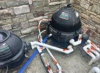
Drain all the equipment on the pad (pump, filter, heater) and reseal all drain ports. This is less water you have to push through the system.

Start on the suction side close all but 1 skimmer valve. Blow that skimmer until very little or no mist is blowing out of it. Close that valve and move to the next skimmer and blow it until very little or no mist is blowing out. Close that valve. Open the main drain and blow it….you will see a lot of air coming up from the drain. After a minute or two, close the valve while the cyclone is still blowing to air lock it.

Pump or pour a couple gallons of antifreeze in each skimmer pipe. I usually open the skimmer valve to let the AF flow easily then close the valve. (I use a pump but it’s not necessary). Seal the skimmer with a gizmo or plugs. Then pour AF in each skimmer body to fill it. If you use gizmos your done there. If you use plugs, put an empty but capped AF bottle in the skimmer body to absorb any freeze movement. You can weight the bottle with some gravel or crush up another empty AF bottle and use it as a wedge to hold the floating bottle in the middle of the skimmer body.

Move to the return side. Plug all but one return farthest from the pad. Start the cyclone and let it blow. When all the water has evacuated that return, unplug the next closer return, and plug the farther one. Let the cyclone blow the entire time. Once this return is dry, unplug the next closest and plug the previous one. Keep repeating until all returns are dry. For good measure after the closest return is dry, I go back to the farthest and unplug it, plug the closest and let it blow a little more.

3. Once the pipes are clear of water, I noticed from the attached photo that there’s no valve on the return line and the robot line. My concern is, when I remove the drain plugs from the heater, pool robot, etc., the air in the pipes is going to escape, causing water to backflow into the main and robot lines? Could this be a problem?
If you keep the cyclone blowing the whole time in the way I described above it won’t be a problem. That line is its own independent line and the pressure from the cyclone will keep any water at bay until it’s blown out.

For good measure once all the returns are dry, you can plug all the returns and open the heater drain and blow it. Then the filter drain. Remove all drain plugs from all equipment and leave them open.

At this point I will pump a couple of gallons of antifreeze in each return pipe at the pool and plug them. You can also gravity pour with a funnel, but it’s slightly less effective than using a pump with a bladder.

On the water fall pump, it would be similar but you’d blow the drain from the port behind the check valve and close its valve while the cyclone is blowing. Blow the fall itself from the impeller side. I see no good way to inject antifreeze into it, so just pull the pump plugs and put the lid back on.

What is your filter setup? Carts with a drain valve with the lay flat hose attached to the drain?
 

Enjoying this content?

Support TFP with a donation.

Give Support
Thread Status
Hello , This thread has been inactive for over 60 days. New postings here are unlikely to be seen or responded to by other members. For better visibility, consider Starting A New Thread.