Help! Repaired Aquarite SWG went up in Flames... LITERALLY!

Hello,

I’m new to the forum. I am, also, a relatively new pool owner. It came with the home I bought about 1 1/2 years ago. The pool/equipment is ~14 years old (except for the Intelliflow VS pump I had installed about a year ago). The previous owner of the home did not replace his salt cell after it failed several years earlier and just had his pool service manage the chemistry manually. He left me a new replacement Optimum Simple Cell, which I installed and switched-on over a year ago when I took over the pool care, shortly after the home purchase.

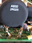
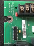
About 6 weeks ago, after over a year of a having a ‘trouble-free pool’, I noticed some algae growth in the pool and discovered that the original Goldline Aquarite (see model # in photo below) was not functioning. After researching the issue I performed the thermistor (AS32 2R025) swap on the board (I did it the “easy” way by snipping off the old legs and soldering the new legs to the old (see photo)). I fired it back up and it worked fine for over a month.

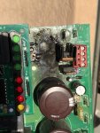
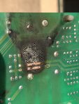
Last week I noticed algae growth, again, and found that the Aquarite had failed for a second time, only this time, it was my solder joint that had failed. It appeared that the solder had melted, opening the connection on the thermistor legs (I’m not very accomplished at soldering). A buddy of mine, who repairs electronic equipment, re-soldered the joints more soundly and we plugged it back in. The rejoice of the “generating” LED coming on was quickly stifled by the panic when thick black smoke began to emminate from behind the faceplate! We d/c’d the power to the panel immediately. The damage is seen in the photos below.

I have several questions that I could use some help with:

*Is anyone aware of this ever happening to an SWG panel?
*Could this be caused by the off-brand salt cell? An internal short?
*Any ideas on the cause? Shorted solder joint? Too much current draw from
another component? Thermistor failure? Transformer failure? Something melted
or shorted during the repair?
*When replacing the board, which model/version should I purchase.
*Should I replace the transformer and/or the salt cell, as well?
*Are there any current readings that I should take on the power supply to diagnose or rule-out causes?

As you may guess, I’m a little leary about having this happen again, since it could have spread to the house if unattended.

Any help that you can give me would be greatly appreciated!

-Steve

BTW: I just noticed that the equipment listed in my signature info is not completely correct. I have the Aquarite, not the Intellichlor system. And, as I mentioned I replaced the single speed pump.
 

Attachments

  • B0968DD0-AF1B-4D75-9311-28E42792377B.jpg
    B0968DD0-AF1B-4D75-9311-28E42792377B.jpg
    42.4 KB · Views: 122
  • 16FA0604-E0D2-4547-A8A3-00CD10C042E0.jpg
    16FA0604-E0D2-4547-A8A3-00CD10C042E0.jpg
    62.2 KB · Views: 121
  • CE1DCD14-D8E5-4FCD-A71C-F1FF4BE91065.jpg
    CE1DCD14-D8E5-4FCD-A71C-F1FF4BE91065.jpg
    54.6 KB · Views: 122
  • 3E29331F-E6D8-4BA4-AE4D-5C17AC8BE967.jpg
    3E29331F-E6D8-4BA4-AE4D-5C17AC8BE967.jpg
    55 KB · Views: 124
Edit your signature. Go to Settings, Edit Signature.

No help on the bonfire. Others will chime in on that!!
 
Steve, I love Valley Center except going near the vicinity always made me broke, big time!

Quick answer: Your PCB is toast! Others may disagree but I would strongly suggest for you to replace the main board GLX-PCB-RITE. I am not familiar with your salt cell, but others can chime in.

As an aside, am I right to assume the 20 Amp fuse did not blow? You mentioned your buddy is an Electronics Tech, did he get the chance to diagnose why it went up in smoke? I strongly believed you failed to clean the carbon deposits on the PCB when you replaced the thermistor the first time. I am not going to argue , but it it were mine I'll go ahead and brush off the carbon deposits with gasoline. The outcome of completely removing the burnt spot as I can tell, will certainly leave behind a big hole on the PCB.

Disconnect any external connections to the main PCB including the display bd. Test the Bridge rectifiers. With the thermistor removed, probe the resistance between the Black terminal (E10) and the thermistor solder pad farthest from the RED terminal. I have not done troubleshooting over the internet but the resistance should not be of anything closer to zero. So lemme know what you got!

Next make sure, nearby diodes checks out and the 24V and 5V regulators are good. Hope you know how to test those components. I might be talking to myself so let's stop here for now and lemme know how you would like to proceed.
 
Thanks for the reply, Meadow. I don’t think I would feel comfortable putting that board back in, even if it were able to be repaired! I was about to order the new board, but hesitated because I wasn’t 100% sure that the GLX-PCB-RITE was the correct replacement. I, also, don’t want to spend a couple hundred bucks on on new board just have it burn up again (If I want to throw my money away, I’ll meet you at the local casinos!) ;) I can live with the fact that I/we screwed up the thermistor repair. I just want to rule-out some other causes before ‘firing-up’ a new board.

BTW; You are correct in assuming that the 20A fuse is still alive and kicking. Obviously, the current through it was within spec.

I own a pretty cool multi-meter (thanks HFT!), but testing diodes and rectifiers might be a little bit above my pay-grade (I’m a firefighter/paramedic), but I’ll get my friend to swing by again and do a post-mortem exam on the old crispy critter and I’ll post his results. That might be a week from now, though...

Thanks, again, for your thoughts!
 
Steve,
The correct replacement main board is GLX-PCB-RITE. Suggest you buy from a vendor who offers a good warranty. Please refer to the below steps 1 & 2 before you install the new main board.

Overtime, the thermistor on a brand-new board will eventually cracked, crumbled or worst case, overheats and burn. These are the normal traits of the inrush current limiter or suppressor when they failed.

Confession; I used to work for a big organization for many years, designing and constructing machines and deployed them worldwide. Each machine has 2 ea, AS32 2R025 in series with the incoming AC supply and they are controlled items per contract. The high thermistor failure rates keep our field techs job secured, replacing thermistors by the hundreds in a week. They are not soldered but screwed on a ceramic bus bar secured by heat/fire resistant pigtails. Some failed within days while others lasted for months or even a year.

The self-heating of a thermistor during operation depends on the load applied and the applicable dissipation factor. Coupled that with extremely high ambient temperature inside the enclosure. The heat developed during operation will also be dissipated through the lead wires and would cause burnt marks on the PCB. When mounting the thermistors, you have to ensure that there is an adequate distance between the thermistor, the PCB and all surrounding parts which are sensitive to heat or combustible.

In your case, it might just be a bad thermistor. You can try to salvage your old PCB as a backup.

  1. Set your DVM to measure AC Voltage. The 2 yellow wires coming out of the x’former should read 24 VAC when power is applied.
  2. The red and black wires coming out of the bridge rectifiers should read 22-24 volts DC or 30-32 volts DC if connected to a known working main board when not chlorinating.
  3. It is imperative to remove the carbon deposits off the board and repair broken tracks, if any.
  4. Test those components I mentioned in my previous post just to make sure they are good or else, the thermistor will get burn instantly due to overload.
  5. Solder the replacement Thermistor in the manner as mentioned above.
  6. Next, the moment of truth! Close your eyes and cover your ears before you turn on the AC power.

Seriously, I admire you and appreciate everything you do at work. You may not hear this often but I thank you for your service.

I may have missed something but let’s hear from others.
 
Once again, your expert advice is greatly appreciated, Meadow! I will test the transformer before firing up the new board and I'll try to check the other components on the old board, as well.

You don't think there's any chance of the salt cell being the culprit of the meltdown, do you?

I appreciate your gratitude for my service. When I got into public safety over 3o years ago it was because I had a passion for it. Then, I learned that people will pay you to do it! :cool: It is, still, nice to here that we are appreciated!

I'll let you know the test results and how the new board works, as soon as they give me a day off to tackle it.
 
Talk to Hayward, I believe you will find a lot of the failed thermistors happen on boxes that are flush mounted inside pool houses. The heat sink can’t only do so much and air movement in a confined placed limits it. If mounting inside, premount two pieces of trim so that when screwed on, the back of the box has 1” clearance.
 
You don't think there's any chance of the salt cell being the culprit of the meltdown, do you?

Steve,
Sorry but I cannot make any suggestions and/or recommendations when it comes to a salt cell. Salt cells of any make and models are fairly new to me and way beyond the level of my expertise in electronics.
I am quite new to pool ownership. I am here to pick from others and share what I've learned in return. This is what this forum is all about.

Let's just keep the door open for the experts here to jump in. Thanks!

added: from my understanding, other members bring their salt cell to a pool store capable of performing functional test. This approach might help in addressing your concerns about your salt cell. Btw, it's VVC day for me :gone:
 
Last edited:

Enjoying this content?

Support TFP with a donation.

Give Support
I just spoke with tech support for my Optima Simple Cell salt cell (Optima Pool Technologies in Corona, CA). The tech assured me that their salt cell would not be the culprit of my melt-down. He said that, even if cross-wired or not plugged in correctly, it would not have caused a shorting or excessive current draw from the board.

Also, I just received the new Hayward replacement PCB. It now requires you to choose which model of Hayward T-Cell before plugging the cell into the board. Knowing that the Simple CelI is compatible with the Aqua Rite, asked the tech which setting I should choose to work with it. He said that T-15 is the correct setting.

I’m heading out to replace the board. I’ll be crossing my fingers as I ‘fire’ it up... Hopefully no ��!
 
Success!

I attempted to measure the transformer and rectifier(s) voltage with the new board before plugging in the SC., but, I’m not real good with the multimeter, especially with live voltage. The meter only gave me .02 volts DC on the yellow wires out of the transformer when I powered it up (I didn’t have everything hooked up yet, so that’s probably my mistake). I didn’t get anything across the rectifiers but, again, probably my not knowing what I’m doing...

Bottom line is; the new PCB is installed and tracking Hot, Straight and Normal (you Navy guys know what I’m talking about).

I thank you ALL for your advice... especially Mr. Meadows.
 
Hi Steve,

Glad to know your SWCG is up and running! Sorry for the delay, went out again to VC & HR yesterday. But once again, I came home this morning naked :cry: And yeah, I can drive on that stretch of the road blindfolded.

For clarification, the 2 yellow wires from the transformer carries AC voltage and not DC as mentioned in Step 1 above. And not necessarily connected to the rectifier or the board when conducting the voltage test. But since all is good now, Congratulations for job well done and good luck in putting life back to the burnt spare board on your freetime. :cheers:
 
Thread Status
Hello , This thread has been inactive for over 60 days. New postings here are unlikely to be seen or responded to by other members. For better visibility, consider Starting A New Thread.