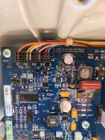
My pool was turning on at odd times, far off schedule, and eventually I determined the clock had gone crazy. It seemed to run very slow at first - and now it doesn't run at all.
I saw a similar thread that troubleshooted the problem right down to the problem 'Real-time Clock' chip and/or relevant Capacitor. [Aqualogic Losing Time?].
Understood I can perhaps replace the entire circuit board (~$450) but if someone could help, I'd like to first try swapping just the electronic components ...
The control board has several labels (1. G1-066082A-1 REV B; printed onto the board); (2. G1-011082A-1T; 1404B; Rev B; green label at left); (3. G1-015082A-1B; 1414; 04684; bar code label at left); and (4. 090037-100-01 1414; white label at the bottom).
The other post mentioned U2 was the real-time clock and this one could be the same (8-pin). There's a second 8-pin "U5" near U2 though so not sure what that one is for. There is a "C8" capacitor that looks like a small toy wheel in a wrapper; 0.33F & 5.5V. (It's 0.33F and not 0.33uF, by the way, as discussed in the other thread.) This capacitor and the area around it looks a little discolored, heat-damaged, but not totally scorched.
The controller doesn't forget the time and settings even with no power for 5 minutes. I'm guessing ... this is an indicator the Capacitor is actually okay, but the real-time clock (8-pin) chip is not working? Or another component that drives the timer.
Oh, and this I don't understand: there is also a U1 (28-pin), U2 (8-pin) on the display circuit board. I don't see any capacitors on that board considered enough to keep the clock during power loss. My focus is on the control board "U2" and "C8" ... but should it be?
Any and all helpful tips appreciated!! Thanks ...


![IMG_3466[1].JPG](/data/attachments/231/231597-8b73ac9f12aa5ba6c8a7eb95f741f030.jpg)

