Hayward Automation Differences (AquaPlus, ProLogic)

Thanks James W!

Thank you also for posting the various tests. I did all of the terminal block tests you posted above. Unless I am not understanding this correctly, there is no power to the external control once the block is removed so I am unable to see if the Comm Error has cleared? To me, this may be the test for the main screen attached to the main board. Am I missing something?

I did the power cycle test - power down and wait 10 minutes then restore power. No change.
I then tested continuity on each of the 4 wires going from terminal block to external control - no issues were found. I visually inspected the 4 wire lead from board to external control - nothing irregular found.
I also tried a different terminal block in the current blocks place - no change.


Thanks.

Eric
 
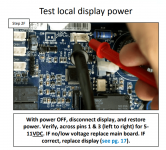
Does the Comm error show up on the local display?

If yes, try the test to see to see if the error clears from the local display.

Try disconnecting the blocks except for the remote display.
 

Enjoying this content?

Support TFP with a donation.

Give Support
Bring the new remote display out to the box and connect it directly with a short set of wires.

If it still does not work and removing the other terminal blocks does not help, then it looks like maybe a bad main board.

Check the back of the main board for any obvious damage.

The board is not that old, so it seems unlikely that it is bad, but it might be bad.
 
Thanks James. I really appreciate all your help in troubleshooting. The remote display is showing a readout, albeit "communication error" but it is displaying something none-the-less. We also purchased a new display and tried that one as well. The error is still there, meaning I am lead to believe it is not the remote display. Can the remote display run off the main display plug, if I connected the 4 wires to the plug prongs. This might give me insight into whether that port on the board is bad. (Does the main display have to be connected for the whole system to work? Or, in this case the main display would be the external display for the test.)
 
Can the remote display run off the main display plug - meaning could I just run the external display from the main display port to test the connectivity to that display?
That's a good question, but I do not know.

I would suspect that the remote display might be able to work from the local display connection or one of the comm ports.

You can try at your own risk if you want.
 
See if the error clears with the local display disconnected.

I think that the local display and the Com connections are the same except that the local display connection is upside down compared to the Com connectors.

All of the connections are 10 or 11 volts DC.

Two of the wires are power and two are data.

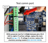
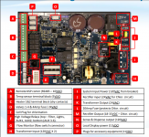
On the Comm connectors (P), pins 2 and 4 are power (left to right) and 1 and 3 are data.

On the Local Display (O), pins 1 and 3 are power and 2 and 4 are data.

For the remote display (A), I suspect that the two outside are power and the two middle are data.

Verify that you have 10 VDC on the two outside wires for the remote display.

I think that if you get the power and data wires correct, it will probably work.

Make sure that the polarity of the power supply is correct.

I am not sure that it will work, so you can do it at your own risk if you want.


1628349524458.png
1628349669638.png
1628349833991.png
 
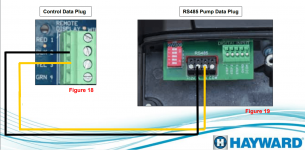
This shows that the two center wires are data and the two outer wires are power.

Red (1) is +12 volts DC and Green (4) is ground (-).

Test the remote display pins 1 to 4 for 10 to 12 VDC.

Put the Red test lead on the Red (1) pin and the black test lead on the Green (4) ground pin.

The meter should show + 12 VDC.

Test the Comm port pin 2 to 4 with the red lead on pin 2 and the black lead on pin 4.

If you get +12 VDC, then you know that pin 2 is (+) and pin 4 is ground (-).

If you get -12 VDC, then you know that pin 4 is (+) and pin 2 is ground (-).

The data wires are probably reversible but try them both ways.

The voltage is the same, so I think the risk is low, but this is experimental and you might get unknown problems.

In any case, do this at your own risk.

1628352392670.png
 
If you are getting the correct voltage at the remote display connection, you can probably just move the data wires to the data pins on one of the Comm terminals or the local display terminal.

This is experimental and there might be unknown problems.

Do at your own risk.
 
Thread Status
Hello , This thread has been inactive for over 60 days. New postings here are unlikely to be seen or responded to by other members. For better visibility, consider Starting A New Thread.