- Nov 12, 2017
- 12,636
- Pool Size
- 12300
- Surface
- Plaster
- Chlorine
- Salt Water Generator
- SWG Type
- Pentair Intellichlor IC-40
As Pentair IntellipH (IpH) automatic acid dosing system owners know, the IpH depends on a Pentair IntellliChlor (IC) saltwater chlorine generator. The IpH uses the IC's power supply, and monitors its flow switch, so that it won't dispense acid if the IC is reporting low flow. Unfortunately, it also monitors the IC's water temperature reading, and won't dispense acid if the IC is reporting cold water. Not sure why Pentair chose this limitation, but I didn't like it. It's bad enough I lose my SWG in the winter, not cool that I lose my IpH, too. So I developed a little circuit that circumvents this issue. It's not really a hack, in that I didn't alter any software or firmware, I just modified the way the IpH and IC are wired together.
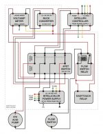
Basically I'm using a switch that bypasses the IpH controller and connects the IpH pump motor directly to the IC's power supply, via an EasyTouch relay for scheduling. Simple enough, but, of course, I never do anything nice... and easy.
 First step was accessing the IC's power supply.
I was cursed with an EasyTouch PSL4 (ET), which along with other limitations, didn't house an IC transformer or any circuit breakers. My IC Power Center was in a separate, external box, bolted to the wall next to my ET. That always bugged me, so I fixed that too. I disassembled the Power Center and moved its guts into my ET. I'll spare you all the details of that, but I can share if someone wants to know how that's done. It ended up looking like so. This is the inside of my ET, and that's the Power Center transformer with its little circuit board mounted above it.
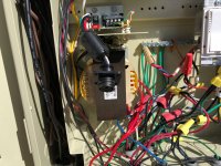
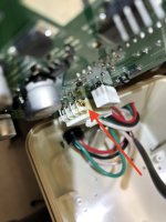
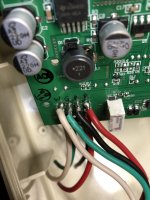
BTW, in addition to selling me the wrong ET, you get a glimpse of the fine wiring job that was done by my nincompoop pool guy. I digress. The connector you see hanging off the Power Center's circuit board was cut off and relocated in the bottom of the ET raceway, where it would be had the ET come this way. Just a matter of extending the wires.
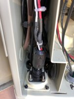
I ended up later moving the Power Center's circuit board elsewhere, up by the ET mother board. I debated whether is should be in the high voltage area, or the low voltage area. I moved it mostly for the convenience of wiring.
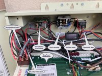
Next step was to mount the other components I needed. The IC's Power Center outputs DC, but the spec's say "22-39VDC." The IpH pump gets 24VDC. The pump might be OK with 22-39V, depending on how close to 24V that means, but I didn't want to risk that, so I found a circuit on Amazon that solves for that. It's called a Buck Converter, and it accepts DC and regulates it to a selectable voltage. It can also regulate the amps, but I didn't utilize that part of the circuit. I also installed a volt/amp display, so I could monitor both, which made adjusting the Buck Converter very easy. I also needed a relay for a flow switch, more on that later. I mounted all that in the low-voltage area of the ET, just behind the motherboard. Like so (also shown is the location I settled on for the Power Center's circuit board):
The Power Center is still wired to the ET's "Pool" circuit, so theoretically the rewired IpH pump won't run unless the filter pump is on and running. But I like the added safety feature of the IpH monitoring the IC's flow switch, so I had to recreate that because with my IpH and IC in winter mode, that feature no longer exists. I installed a flow switch in my plumbing. Luckily I had just barely enough room. But the flow switch wires we're of a very small gauge, so I used a relay to solve for that. The current that the IpH pump motor draws runs through the relay. The current that runs through the flow switch and its wimpy wire is only what is required to close that relay.
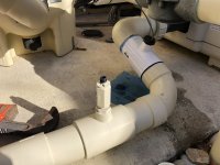
I found a good spot for the flow switch, just in front of the IpH injector, and protected from anything that might snag its small wire.
Then I had to find a spot for the "IpH Winter Switch" (see above for the backside view). I needed a 4PDT switch (four-pole, double-throw), that was heavy duty and that could handle the current. It was kinda a honker. I thought about mounting it in the bottom of the ET, but that would have meant low voltage DC wiring in the high-voltage AC area of the ET, plus there are twelve wires involved, going back and forth between the switch and all those components in the low-voltage area. I didn't like that idea, and while I was loathe to punch through my ET's faceplate, that's what I ended up doing. I had to file down the switch handle, to clear the ET's door!
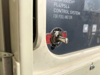
I chose that spot because of what was behind it, but also because it didn't look too bad. Unfortunately, I later upgraded my ET motherboard to an ET8, and replaced the faceplate. Not so OK-looking anymore. Oh well.
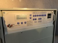
Lastly, I wired everything up, held my breath, turned it on and... it worked (for a while anyway, more on that in post #3 below). The next post goes into the details of the actual wiring, but the abridged version is the switch has three-positions:
In the middle position, power is disconnected from both the IC and the IpH, and the IpH pump motor is disconnected completely. It's like a stand-by mode, or "everything off" mode.
In the right position, the IpH and IC are connected to the IC Power Center and function normally together, as originally designed. This is the "Normal Mode" position.
In the left position, or "Winter Mode," power is disconnected from the IC and the IpH, and the IpH pump cable is re-routed. In Winter mode, the pump motor is connected to the Buck Converter through both the flow switch relay and one of my ET relays. The pump motor gets 24VDC only when three things are true: the Pool circuit is on, the ET's Aux 2 feature circuit is on (which closes the ET relay) and the flow switch is closed. I just schedule the Aux 2 feature circuit within my Pool circuit schedule, for the desired duration, and the IpH pump runs (1 minute minimum or longer, in 1 minute increments). This ran all winter with no issues and my pH stayed right where I want it without me having to manually pour acid. Nice.
The only safety feature missing from what the IpH normally provides, is the dispensing limit. In normal mode, the IpH will only dispense a limited amount of acid each hour. I don't know the exact amount, but it's like a few ounces (it's in the IpH manual somewhere). In my Winter mode, there is no limit. It'll pump whatever the ET schedule dictates. Potentially, the ET schedule could malfunction and empty the entire contents of the IpH into the pool. To be fair, theoretically, the IpH could also malfunction in that same way. Either way, it wouldn't be catastrophic for my pool. At most my IpH holds 2 gallons of 31% Muriatic acid, and of course it's not always full. Sometimes it's only a quart, or less. But even worse case, two gallons will only crash the pH for a short while, without causing any damage to the pool. Now folks that have built similar acid dispensing systems using Stenner pumps with 15+ gallon tanks are asking for trouble. Two gallons of acid poses no real threat.
Additionally, because Winter Mode disconnects power from both the IpH and the IC, I no longer have to do that physically. I used to pull the fuse from the Power Center so that the two weren't powered on for nothing all winter. Now that happens with the flip of the switch.
I could have simplified all this and just eliminated the IpH controller all together. Acid injection would occur all year long using just the ET relay and ET scheduling. No switch needed. But I like the fact that the IpH with its controller dispenses a small amount of acid hourly, all day long, and turns off the IC while it's injecting. To recreate all that, I'd need more ET scheduling slots than are available. I really like the way the IpH and IC work together most of the time, I just wanted the IpH to work in the winter, too.
Basically I'm using a switch that bypasses the IpH controller and connects the IpH pump motor directly to the IC's power supply, via an EasyTouch relay for scheduling. Simple enough, but, of course, I never do anything
I was cursed with an EasyTouch PSL4 (ET), which along with other limitations, didn't house an IC transformer or any circuit breakers. My IC Power Center was in a separate, external box, bolted to the wall next to my ET. That always bugged me, so I fixed that too. I disassembled the Power Center and moved its guts into my ET. I'll spare you all the details of that, but I can share if someone wants to know how that's done. It ended up looking like so. This is the inside of my ET, and that's the Power Center transformer with its little circuit board mounted above it.

BTW, in addition to selling me the wrong ET, you get a glimpse of the fine wiring job that was done by my nincompoop pool guy. I digress. The connector you see hanging off the Power Center's circuit board was cut off and relocated in the bottom of the ET raceway, where it would be had the ET come this way. Just a matter of extending the wires.

I ended up later moving the Power Center's circuit board elsewhere, up by the ET mother board. I debated whether is should be in the high voltage area, or the low voltage area. I moved it mostly for the convenience of wiring.
Next step was to mount the other components I needed. The IC's Power Center outputs DC, but the spec's say "22-39VDC." The IpH pump gets 24VDC. The pump might be OK with 22-39V, depending on how close to 24V that means, but I didn't want to risk that, so I found a circuit on Amazon that solves for that. It's called a Buck Converter, and it accepts DC and regulates it to a selectable voltage. It can also regulate the amps, but I didn't utilize that part of the circuit. I also installed a volt/amp display, so I could monitor both, which made adjusting the Buck Converter very easy. I also needed a relay for a flow switch, more on that later. I mounted all that in the low-voltage area of the ET, just behind the motherboard. Like so (also shown is the location I settled on for the Power Center's circuit board):

The Power Center is still wired to the ET's "Pool" circuit, so theoretically the rewired IpH pump won't run unless the filter pump is on and running. But I like the added safety feature of the IpH monitoring the IC's flow switch, so I had to recreate that because with my IpH and IC in winter mode, that feature no longer exists. I installed a flow switch in my plumbing. Luckily I had just barely enough room. But the flow switch wires we're of a very small gauge, so I used a relay to solve for that. The current that the IpH pump motor draws runs through the relay. The current that runs through the flow switch and its wimpy wire is only what is required to close that relay.

I found a good spot for the flow switch, just in front of the IpH injector, and protected from anything that might snag its small wire.
Then I had to find a spot for the "IpH Winter Switch" (see above for the backside view). I needed a 4PDT switch (four-pole, double-throw), that was heavy duty and that could handle the current. It was kinda a honker. I thought about mounting it in the bottom of the ET, but that would have meant low voltage DC wiring in the high-voltage AC area of the ET, plus there are twelve wires involved, going back and forth between the switch and all those components in the low-voltage area. I didn't like that idea, and while I was loathe to punch through my ET's faceplate, that's what I ended up doing. I had to file down the switch handle, to clear the ET's door!

I chose that spot because of what was behind it, but also because it didn't look too bad. Unfortunately, I later upgraded my ET motherboard to an ET8, and replaced the faceplate. Not so OK-looking anymore. Oh well.

Lastly, I wired everything up, held my breath, turned it on and... it worked (for a while anyway, more on that in post #3 below). The next post goes into the details of the actual wiring, but the abridged version is the switch has three-positions:
In the middle position, power is disconnected from both the IC and the IpH, and the IpH pump motor is disconnected completely. It's like a stand-by mode, or "everything off" mode.
In the right position, the IpH and IC are connected to the IC Power Center and function normally together, as originally designed. This is the "Normal Mode" position.
In the left position, or "Winter Mode," power is disconnected from the IC and the IpH, and the IpH pump cable is re-routed. In Winter mode, the pump motor is connected to the Buck Converter through both the flow switch relay and one of my ET relays. The pump motor gets 24VDC only when three things are true: the Pool circuit is on, the ET's Aux 2 feature circuit is on (which closes the ET relay) and the flow switch is closed. I just schedule the Aux 2 feature circuit within my Pool circuit schedule, for the desired duration, and the IpH pump runs (1 minute minimum or longer, in 1 minute increments). This ran all winter with no issues and my pH stayed right where I want it without me having to manually pour acid. Nice.
The only safety feature missing from what the IpH normally provides, is the dispensing limit. In normal mode, the IpH will only dispense a limited amount of acid each hour. I don't know the exact amount, but it's like a few ounces (it's in the IpH manual somewhere). In my Winter mode, there is no limit. It'll pump whatever the ET schedule dictates. Potentially, the ET schedule could malfunction and empty the entire contents of the IpH into the pool. To be fair, theoretically, the IpH could also malfunction in that same way. Either way, it wouldn't be catastrophic for my pool. At most my IpH holds 2 gallons of 31% Muriatic acid, and of course it's not always full. Sometimes it's only a quart, or less. But even worse case, two gallons will only crash the pH for a short while, without causing any damage to the pool. Now folks that have built similar acid dispensing systems using Stenner pumps with 15+ gallon tanks are asking for trouble. Two gallons of acid poses no real threat.
Additionally, because Winter Mode disconnects power from both the IpH and the IC, I no longer have to do that physically. I used to pull the fuse from the Power Center so that the two weren't powered on for nothing all winter. Now that happens with the flip of the switch.
I could have simplified all this and just eliminated the IpH controller all together. Acid injection would occur all year long using just the ET relay and ET scheduling. No switch needed. But I like the fact that the IpH with its controller dispenses a small amount of acid hourly, all day long, and turns off the IC while it's injecting. To recreate all that, I'd need more ET scheduling slots than are available. I really like the way the IpH and IC work together most of the time, I just wanted the IpH to work in the winter, too.
Last edited:


