GFCI Breaker for Main Pump Test Button Doesn't Work

Chappie

Well-known member
Apr 25, 2016
51
Lafayette, LA
My main pump is on a 2 pole 20 amp GFCI breaker. Current flows and everything for the pool works properly, but if you press the TEST button when the CB is on, it should trip it. It doesn't. I think it's not providing the GFCI protection that is required.

My plan is to replace the breaker. I've found this one on Amazon that looks the same and is the same brand (which I've read is important), but I know looks can be deceiving.

I feel fairly confident that this is the right one, but on the existing one all of the identification stickers are worn off, so I'm really just guessing. Can anyone provide any insight, or does it look like I'm on the right track?
 
Most breakers should list what breaker boxes they are compatible with.
Look at the breaker housing and see if you can find a name like Eaton, Murray or Siemens. (there are many more)

As long as the breaker you buy is listed as compatible with whatever breaker box you have, it should work.
 
I don't know enough about it to argue competently, but the description says it is 120v, and also people in the questions and reviews are saying it's 240. I know some things can handle both, I assume this is one of them. I also saw a video yesterday that said the voltage coming into the panel is typically 240v, and it just depends on how you set it up that determines whether 120 or 240 comes out.

There may also be 120v variable speed pumps, but I guess I'll look into it more when it comes to replacing the current one.
 
IMG-4128.JPG

To the right is my timer. The wires on the bottom, just left of center lead to my booster pump. The wires from the bottom left and the top appear to lead back to a sort of terminal box that I assume is fed from the main panel. For some reason the top wires take a trip up some hard conduit into the attic. The bottom wires connect to that "terminal box" through a flexible conduit. Is the red wire that's wrapped in white the neutral that you mentioned?

I think it's awfully messy, but maybe that's just how things are done? i also don't like how much bare wire sticks out of the bar on the right for those two neutral (I think) wires. I guess I could have trimmed them.

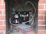
The new breaker is the one on the top left, and it is working and trips properly when you hit the test button, so yay for that.
 
Last edited:

Enjoying this content?

Support TFP with a donation.

Give Support
What timer do you have?

Do you have a picture of the motor label?

All you should need to do is move the wire from the center terminal of the breaker to the outer terminal and bypass the timer if the timer is 120 only.

Can you measure the voltage at the breaker outer terminals?

The outer terminals should be labeled "Load Power". Measuring the voltage at the two outer terminals should be 240 volts.

Is the center terminal labeled "Load Neutral"?
 
Last edited:
The terminals are labeled as you suggest. Where do i touch the probes for my multi-meter to test for 240v correctly?

I don't currently have a 240v motor that I am installing. When my last motor died, I bought one after a long consultation with a customer service rep at a prominent online pool supply company. The only question she didn't ask is whether I had 120 or 240v. At the time, the best I could figure was that I had only 120v, so I returned it and got another 1-speed motor. I have a very unlucky history with pump motors, so I assume the next one will be coming soon, and if I can put a 240v motor in with my current set-up, I'm definitely going to.
 
Put the leads on the "Load Power" terminals. With one lead on the top terminal and the other lead on the bottom terminal, you should read about 240 volts.

Does the pump motor label say 115 volt only or 115/230?

Is the timer a 115 or 230 volt timer?
 
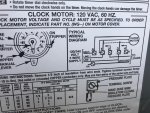
Here's the label on the timer. I thought it was 120 only, and maybe it is, but the diagram on the right seems to indicate that it can handle 240?

pool timer.JPG

So putting the leads on the outside terminals of the breaker gives me a reading of "1". If I do top and neutral or bottom and neutral, I get 120.

I did notice something that I had never seen before though - if you look back at the pic of my breaker box, the bottom breaker is wired like you indicated - white and black wires to the outer "Load Power" terminals. There's also a bare ground wire plugged into the ground bar on the left. This breaker is hooked straight to a 230v booster pump.

If I had noticed this when I had the 230v multi-speed main pump in my possession, I might have realized I actually could have used it. I was thrown when it said "Connect the white, black, and green wires to terminals x,y, and z" and all i had was red wire.

It looks to me, like all I'd need to do is get a little bit of the proper white/black/green wire and run it to the timer and then from the timer to the pump, and I'd be in business.

Per the intermatic site it looks like I would have to replace the timer back to a t104r, which was what came with the house, but now looks to be the wrong voltage for what I was feeding it, and may explain why 2 have died in 3 years.
 
What voltage setting are you using on the multimeter?

Make sure that it's set to AC volts higher than 250.

Measuring at the two incoming black and red terminals at the top or at the double breakers "Load Power" terminals should read 240 volts.

The timer clock takes 120 volts. So, the clock gets power from terminal "A" and terminal 1.

Do you have a picture of the timer wiring?

You can use the timer for 240 volts by wiring Line power to terminals 1 and 3 and Load power to terminals 2 and 4. You would run a white neutral to Terminal "A".

Does the motor label say 115/230 or only 115 volts?
 
Do you have a picture of the timer wiring?

You can use the timer for 240 volts by wiring Line power to terminals 1 and 3 and Load power to terminals 2 and 4. You would run a white neutral to Terminal "A".

Does the motor label say 115/230 or only 115 volts?

The above picture is the only wiring guide there is.

The booster pump is 230 only, the VS pump was 230 only also, but for clarification it was returned long ago.


edit:
Oh, and I do get 244v on my multi meter when it's on the correct setting.

Also, I went and looked at the timer wiring. As far as I can tell, it's hooked up like you describe, with the Line power going into 1 and 3, and the load going into 2 and 4. The only difference is that there's a ground wire running from both sides that is connected. Nothing is connected to A.

So if I'm understanding correctly, all I would need to do is switch the wire that's currently connected to the Line Neutral middle terminal to the outer Line Power terminal, and the run a new (white presumably) wire from the newly vacant Line Neutral terminal to A on the timer.
 
Last edited:
On the main pump and the booster pump does the voltage say 115/230 or 115 or 230?

The clock needs 120, so it must currently be connected to 1 and 3. Do you have a picture of the actual wires in the timer?

To switch to 240, you would need to run a white wire from the breaker "Load Neutral" to "A" and change the clock lead from 3 to "A".

You would then move the breaker middle wire from "Load Neutral" to "Load Power".

Then, you would verify 240 at the pump wires, set the pump to 240 and connect the wires.
 

Enjoying this content?

Support TFP with a donation.

Give Support
Thread Status
Hello , This thread has been inactive for over 60 days. New postings here are unlikely to be seen or responded to by other members. For better visibility, consider Starting A New Thread.