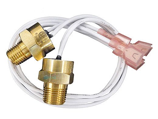
The header assembly is polymer, not metal.
Even if it was metal, the metal takes time to heat up.
Also, you have less than 3 seconds before the water boils.
In my opinion, the high limit is just not going to react that fast.
Try it on your heater if you feel like it won't hurt anything.
Most likely, the heater will start banging very loudly due to the water boiling and the heat exchanger getting expanded and warped.
Copper is very soft and delicate; it will get way too hot if there is no flow for even a few seconds.
Last edited: