Flow Vis H2flow meter/check valve

Jun 14, 2018
132
Long Island NY
I got this flow meter that doubles as a check valve on Amazon for some new pumbing on a heat pump. I figured this was a good way to determine flow coming out of the heat pump so I could maximize efficiency on the pump. I also needed a check valve to use for the bypass.

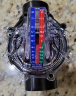
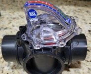
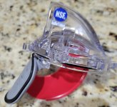
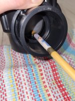
It seems very restrictive by design but I could be totally wrong. The pictures I tried to take show how far the flapper is open at approximately 55 gpm. When you look how little space there is for the water to pass at 55 gpm, I wonder how this cannot be restrictive?

Is the idea behind this device to measure the gpm that's actually hitting the flapper and not how much water is actually moving past it? But if that's true then what's the point of using this since you want that actual amount of flow to go where it needs to go.
 

Attachments

  • 20240510_230340.jpg
    20240510_230340.jpg
    436.7 KB · Views: 4
  • 20240510_230350.jpg
    20240510_230350.jpg
    487.4 KB · Views: 4
  • 20240510_230359.jpg
    20240510_230359.jpg
    377.7 KB · Views: 4
  • 20240510_231521.jpg
    20240510_231521.jpg
    342.6 KB · Views: 4
  • 20240510_231609.jpg
    20240510_231609.jpg
    270.6 KB · Views: 4
You are installing a Heat Pump which is the most restrictive type of heater.

All of the other things you are worrying about for efficiency are rounding errors compared to the HP you are putting in.

Install a Heater Bypass - Further Reading to bypass the restrictions when not in use.
 
If that's the case then putting this flow meter after the heater doesn't make much sense right? Perhaps it should go before the heater and then a regular check valve after the heater for the bypass
It does not matter where you put the flow meter. The flow rate in your entire plumbing is the same.
 
  • Like
Reactions: anthony21078
As Allen points out, with the exception of certain types of bypasses, flow is constant throughout your pad. The velocity of the water might be different at point A vs point B, but the amount of water passing points A and B is the same. So where you put the FlowVis doesn't matter, and it won't cause more or less restriction if you move it.

All check valves are somewhat "restrictive." They all have a spring-loaded flapper that "pushes" against the flow of water, causing some amount of restriction. That is the trade off for the function they provide. But it is minimal. And a FlowVis doesn't cause much more than any other check valve, if any. Moving the FlowVis now, and adding a second check valve is just going to add more restriction. It won't change the amount the FlowVis is causing, but it'll add what the second check valve will cause.

Is the idea behind this device to measure the gpm that's actually hitting the flapper and not how much water is actually moving past it?
I can't quite wrap my head around the first part of that question. The FlowVis indicates how much water is actually moving past it. And as explained, how much water is moving past any point in your pad plumbing. Which means it indicates how much water is moving through your heater, which, I presume, is what you want to measure. It's what my FlowVis is measuring: how much water is moving through the panels of my solar heater. Any type of pool heater will have an optimal flow rate, that which will heat the water most efficiently (heat produced against the cost of heating it). The heater's manual will likely spec the optimal flow rate, the FlowVis will tell you exactly what RPM to set the pump to achieve that flow rate.

But if that's true then what's the point of using this since you want that actual amount of flow to go where it needs to go.
I think I answered that above. The point of the FlowVis is to determine the flow rate through your heater (or anywhere else on your pad).

If I may, you're overthinking this. If the heater manual specs a rate of, say, 40 GPM, then you adjust the RPM of your pump until the FlowVis reads 40 GPM. That's all there is to it. The FlowVis will perform that function no matter where you locate it. So locate the FlowVis where its check valve function makes the most sense.

That's how I use mine. And a solar heater also requires some check valves, so my FlowVis doubles as one of the two I need. It's really the perfect gizmo for our purposes.
 
Last edited:
If that's the case then putting this flow meter after the heater doesn't make much sense right? Perhaps it should go before the heater and then a regular check valve after the heater for the bypass
One thing to be aware of is that if you have a heater bypass and only bypass some of the flow, then you could have different flow rates in different parts of the plumbing. It all depends on how the valves are setup.

Also, the head loss in a FlowVis has approximately the same head loss as a standard Jandy check valve. If you look at a normal check valve, the valve opens further with increasing flow rates much like a FlowVis. They just added a scale to the FlowVis in order to measure flow.
 
  • Like
Reactions: Dirk
One thing to be aware of is that if you have a heater bypass and only bypass some of the flow, then you could have different flow rates in different parts of the plumbing.
Yep, that's what I meant by "with the exception of certain types of bypasses." Here's an example of an SWG bypass:

Screen Shot 2024-05-11 at 10.41.02 AM.png

It's purpose is to dial down the flow to an SWG, in cases where the rest of the system requires more flow than an SWG can handle. In this setup, depending on how the flow control valve is set, the flow through the SWG loop will be less than anywhere else on the pad. If you had two FlowVis, one after your heater, and one in that SWG loop, they would not read the same. That's because the flow is being split in two. Some through the bypass loop, and the rest past the flow control valve.

So, yes, if your heater bypass is going to be doing something similar, and you want your FlowVis to read the flow through the heater, then it's location definitely would matter. But if I understand heater bypasses correctly, they're not intended to regulate flow through the heater, but rather to toggle full flow or no flow through the heater. If that's how your bypass will be used, then we're back to it doesn't matter where the FlowVis is located.

In most scenarios, you would never reduce the flow through a heater. The more flow through a heater, the better it'll heat your water. But the more it will cost. So really you'd want maximum flow through the heater. If you dialed down the flow through a heater with a bypass valve, you'd just be wasting pump energy, and spending more than you need to to heat your pool. I suspect you're just going to use your heater bypass as a flow "on-off toggle."
 
Last edited: