Electrical question

Eriky

0
Jul 4, 2010
60
Not sure if this is the right place for this, but hopefully someone can help me out.

My pool builder put two receptacles both 120V GFI in my pool area, one by the filter, and one on the other side of the pool. It appears my GFI receptacle went bad on one of them. The outlet stopped working, but I pulled it out and verified its getting 120V with a multimeter.

I flipped the breaker and pulled out the old receptacle, and brought it to Home Depot to try to find a replacement. I could not find the exact one, so I bought 2 that seemed the closest. I bought a 120V 20Amp and a 15Amp.

Neither worked, but I again verified I have 120V going to the box.

I have played around with some electrical stuff, but I am not an expert. The one thing that throws me off with this is coming out of the box are 4 wires, black, white and green (ground) as expected, and then there is an extra thin (I think copper) wire with a forked connector on it. On the original receptacle, the green and copper wire seemed to be going to the same place, so I tried to make sure they were both connected to the same spot on the new receptacle.

I have done these before in the house and garage, and never had a problem, so Im not sure what to try next. Not sure what that copper wire is, but assuming some type of extra ground wire?

Any suggestions or ideas? I asked the builder and they are far and want to do a service call, but this seems like something I should be able to do myself.
 
You will have issues if both of them are on the same circuit. I tried that once by accident, I didn't realize the outlet I grabbed power from for a new receptacle had a GFCI up circuit from it. I could not get the GFCI to set.

Another thing to check is if the breaker is GFCI, if so you don't need GFCI outlets.
 
Use a 20amp receptacle with 12 gauge wiring and 15 amp with 14 gauge. If you have some scrap wire laying around use it to compare to what you have.

That small, thin, forked wire sounds like some kind of control wire. What color is it? Where does it lead to in the panel?

Also, is the one breaker controlling both outlets? Are they wired in serial or parallel?
 
Did you wire the incoming power on the line or the load side of the receptacles?
Incoming power has to be wired to the line terminals of the receptacles. the load terminals are used to protect additional receptacles down line.
 
Everyone, thanks for all the replies and help! Much appreciated! Its definitely a 125V 20Amp receptacle. However, the 20amp receptacle I bought is not working. When I checked with the multimeter, I do not remember which side I checked with, I always thought that for AC black and white did not matter. I will try check it again.

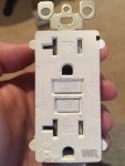
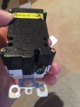
Here is the receptacle that was originally in there that is not working anymore.

If you look at the bottom of the second photo, the thin copperish wire with a forked connector was going to that greenish screw, and the ground green wire was going to that opening above it. I originally assumed they were connected, but looking at it, I don't think they are. I assume I need a very specific type of receptacle for this, but when I went to home depot and lowes, I could not find any that had this type of setup. Does anyone know more specifically what I need to look for so I can order one on line?


IMG_4859.jpgIMG_4861.jpg
 
They are connected. Just two ways to connect the ground. Use your meter in continuity mode to verify. As mentioned before, the lower hot/neutral are for line IN (you can see the stamped 'line' lettering), and the top hot/neutral are for load OUT, or other outlets downstream.
 
Do you have voltage at the wires without them connected? If not you will need to go back to the next junction box (if there are any) and check there. As for the ground connection, that screw is only rated for one wire. There should not be any wires wrapped around the screw, only one pushed straight into the slot next to the screw and the screw clamps the wire. Any additional ground wires need to be attached to the receptacle ground with pigtails and wire nuts. The same goes for the line and load connections. The screws act as clamping devices when you put the wire leads into the push holes in the back of the receptacle. One wire per hole and nothing wrapped around the screw. I have seen these in the past that do not make good connection when wires are on the screws.

Dan
 
First, your replacement outlet should also be marked with a "WR" (weather resistant), same as the old one.

Do you know where that forked thin braided wire comes from? Is it possible it is a ground wire to the metal box? A picture of it would help. If is was connected with the green wire on the old outlet then it most likely is a ground and should go on the green screw terminal but as others have mentioned that terminal is really designed for a single connection.

The following is presuming that you do have good power to the GFCI outlet location

Turn off the breaker feeding the circuit.

You must connect the incoming power to the terminals marked "LINE", Black wire to the Black or Brass screw, white wire to the silver screw of the line side.

Your ground wire (either bare copper or Green) goes to the green screw at the bottom.

If you have additional outlets (non-GFCI) downstream they will be connected in a like manner to the "LOAD" terminals. But by the looks of your old outlet I see that the load terminals still had the tape on them.

Once you are hooked all up and covers installed turn back on your power and press the "reset" button until it locks in... some type require you to hold it for 1-2 seconds, you should then have power

Learn How To Safely Install a GFCI Outlet at The Home Depot

GFCI wiring diagrams

https://www.do-it-yourself-help.com/gfci_wiring_diagrams.html
 

Enjoying this content?

Support TFP with a donation.

Give Support
Thread Status
Hello , This thread has been inactive for over 60 days. New postings here are unlikely to be seen or responded to by other members. For better visibility, consider Starting A New Thread.