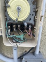
Trying to upgrade from my Intermatic timer . Im not sure if i have the wrong model but i can’t seem to get it to work as its suppose too .
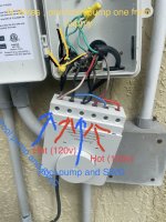
I have two 120v Line wires
Pool pump has 4 wires red,black,white ,green
Chlorinator has 3 red,black, green
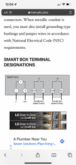
Dewenwils i have has the following terminals
L—N, com1–no1 ,com2–no2
The one picture is the old setup , and the other is new smart box terminal
I have two 120v Line wires
Pool pump has 4 wires red,black,white ,green
Chlorinator has 3 red,black, green
Dewenwils i have has the following terminals
L—N, com1–no1 ,com2–no2
The one picture is the old setup , and the other is new smart box terminal