Converting to VS Pump - finally!!!!

HermanTX

Gold Supporter
TFP Guide
May 20, 2020
6,603
Katy TX
Pool Size
14600
Surface
Plaster
Chlorine
Salt Water Generator
SWG Type
Jandy Aquapure 1400
I have been waiting to convert my single speed to a VS pump for over a year and now ready to do that.
I found a Pentair IntelliFlo VSF pump - part # 011056. States the following parameters
Voltage 230
Full Load Amp 16
Kw 3.2
Hp 3
SF 1.32
SFHP 3.95
Ports 2 x 2
Just want to ask the experts if there are any concerns over this model of VSP. It is only for circulation as I have separate pump for waterfall. currently no SWCG but that is next on my budget list. Currently have the older Jandy AquaLink automation but it states it can program the IntelliFlo VF or the IntelliFlo VS. Any concerns I need to watch for?
I will have a pool tech install to obtain the 3 yr warranty, plus there are some rebates I can get as well.
Thanks.
 
  • Like
Reactions: Rancho Cost-a-Lotta
Herman,

The Pentair IntelliFlo 011056 is a great VSF pump..

I believe that you will find that your automation will only allow you to either use the VS or VF but not both. Not a big deal in my mind... I am not a fan of VF as 99% of users don't need it, so I suggest you set it up as a VS pump.

Also, I suggest that you use pump unions to install it.. They make it easy to install and prevent leaks as they have O-Rings on the threaded connections to the pump vs. thread tape. It should be illegal to install a $1,500 pump without pump unions.. :mrgreen:


Thanks,

Jim R.
 
  • Like
Reactions: HermanTX
Herman,

The Pentair IntelliFlo 011056 is a great VSF pump..

I believe that you will find that your automation will only allow you to either use the VS or VF but not both. Not a big deal in my mind... I am not a fan of VF as 99% of users don't need it, so I suggest you set it up as a VS pump.

Also, I suggest that you use pump unions to install it.. They make it easy to install and prevent leaks as they have O-Rings on the threaded connections to the pump vs. thread tape. It should be illegal to install a $1,500 pump without pump unions.. :mrgreen:


Thanks,

Jim R.
Thanks Jim. One other question - even though I do not have a SWCG, do you see any concerns in running the pump 24/7 (mainly in the summer) or maintain my current 8-9 hrs each day? I know from an energy usage, I may be better off regardless but just thinking about maintaining constant circulation for skimming as I have a lot of leaves blowing in from neighbor trees.
 
Herman,

I have three IntelliFlo pumps (the older 011018) that have been running 24/7 since they were installed.. One is over 10 years old, one is almost 8 years old and the one at my house is about 7 years old. I run 24/7, because I like to generate a little chlorine all the time, and skim all the time.. It is by no means a requirement.. You should run your pump so that it does what you want it to do..

Thanks,

Jim R.
 
  • Like
Reactions: HermanTX
Just a quick update. Installed the IntelliFlo VSF pump (011056). No leaks! Installed pump unions. Have about 11 inch straight run into the pump.
I set 4 programs on "schedule" to allow for skimming and when my pressure side cleaner (using a booster pump) is running.
I need to get into the details as to how it hooks up to my AquaLink automation. I have the older version RS6 and it does have a setting for IntelliFlo VS or VF in the menu. I need to figure out where the cable from the pump to the AquaLink control box needs to be connected. Right now, I just have power to the pump and using the onboard pump programs to set the schedule.

Who uses a AquaLink with a Pentair IntelliFlo pump? My wiring diagram on the panel box of the AquaLink is all old and difficult to read and I do not have any original manuals (I am 3rd owner). I tried searching for Jandy but all seems to be the newer models. Any guidance is appreciated.
 
There should be a couple of red 4 wire terminal blocks along the side of the RS-6 main board. These connectors are the 4 wire RS-485 connections that need to be connected to the intelliflow pump. The intelliflow pump has a two pin RS-485 cable that has green and yellow wires. The green wire goes to pin 2 of the red terminal block and the yellow wire goes to pin 3. See page 26 of the intelliflow manual. While the manual shows the interfacing to a solar controller the RS-6 uses this a]same terminal block with the same wiring pin out. I’m not sure if that pump RS-485 cable comes with the pump or whether it’s an accessory.

Pins 1 and 4 of the red terminal block are +12 volts and ground and shouldn’t need to be hooked up.

Once the pump cable is connected to the RS-6’s terminal block you should be able to go into the iAquaLink setup, select the intelliflow pump and it should be recognized in theory.
 
  • Like
Reactions: HermanTX
There should be a couple of red 4 wire terminal blocks along the side of the RS-6 main board. These connectors are the 4 wire RS-485 connections that need to be connected to the intelliflow pump. The intelliflow pump has a two pin RS-485 cable that has green and yellow wires. The green wire goes to pin 2 of the red terminal block and the yellow wire goes to pin 3. See page 26 of the intelliflow manual. While the manual shows the interfacing to a solar controller the RS-6 uses this a]same terminal block with the same wiring pin out. I’m not sure if that pump RS-485 cable comes with the pump or whether it’s an accessory.

Pins 1 and 4 of the red terminal block are +12 volts and ground and shouldn’t need to be hooked up.

Once the pump cable is connected to the RS-6’s terminal block you should be able to go into the iAquaLink setup, select the intelliflow pump and it should be recognized in theory.
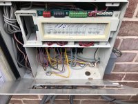
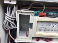
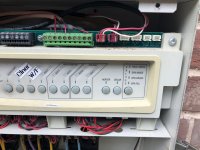
Thanks for your reply. I need some additional clarification and I have included some pictures of my Jandy control box.
It has one 4-wire red terminal block on left side but that is in use by the wireless connector (I did not hook that up but was done previously - many years ago when it was switched to a PDA). All the wire colors match to the terminal bar call out (see the picture of the circuit layout - sorry for the condition but I pulled it off several years ago as it was getting tattered.
My only other equipment connected is a air temperature sensor, a water temperature sensor and a gas heater which are all on the Green terminal block. Then on the far right side are the two connections for the Jandy automated valve controllers needed for spa and mode modes.

Also, what adjustments should I make any adjustments to the dip switches, if any? The #2 dip switch is on 1 speed pump and can be switched to right side for 2 speed pump.

My IntelliFlo manual does not have any info on the solar controller. My page 26 is a trouble shooting page.
Do you have yours as a PDF. My PDF is too large file size to attach it.

Appreciate all your views on this.

Jandy Controller - Circuit Detail.jpgJandy Controller - Open View .jpgJandy Controller - Left Side with Dip Switches .jpgJandy Controller - Center Section.jpgJandy Controller -Right Side with Pin Connectors .jpg
 
It’s the four pin connector on the top left that you want to hook up to. On later RS main boards there are two of those connectors on the main board. In the RS manual it says you can hook up to two wire to each terminal of that connector, in your case it will be your wireless controller and the pump.

Here’s a video that shows how to double up the wires on the terminal block to connect up the pump. I think I gave you the wrong information in the earlier message as it looks like the yellow wire goes to pin 2 (the black wire on the controller) and the green wire goes to pin 3 (the yellow wire on the controller connection).


Here’s the RS manual and the Pentair pump connection wiring is on page 18.


Sorry about that, I don’t have a Intelliflow pump I’m using a Vgreen pump in my system.

I hope this helps
 
  • Like
Reactions: HermanTX
Actually the RS controls the Vgreen just fine. It just doesn’t support control via the RS-485 interface. I’m using the Vgreen’s digital inputs and extra Aux outputs (relays) to select four different speeds. It works great!

On another post here I see that someone linked the API to the Regal Beloit (Century) motors and there are configuration parameters that look to be programmable. One of these selects “protocol type” and the choices are none, Jandy, Pentair, or all. I’m trying to understand the checksum that they use and I bought a USB to RS-485 converter. At some point if I figure it out I may try changing this parameter to Jandy to see if the IAquaLink will then recognize the motor as a Jandy motor. In theory I could do the same thing and set it for the Pentair protocol and see if the iAquaLink then sees it as a Pentair motor. It’s a long shot but the same motor company supplies the motors to all these pump manufacturers so it makes sense the supported RS-485 are just the internal programming.

One day I may get around to this, but for now the digital inputs work great.
 
  • Like
Reactions: duade

Enjoying this content?

Support TFP with a donation.

Give Support
It’s the four pin connector on the top left that you want to hook up to. On later RS main boards there are two of those connectors on the main board. In the RS manual it says you can hook up to two wire to each terminal of that connector, in your case it will be your wireless controller and the pump.

Here’s a video that shows how to double up the wires on the terminal block to connect up the pump. I think I gave you the wrong information in the earlier message as it looks like the yellow wire goes to pin 2 (the black wire on the controller) and the green wire goes to pin 3 (the yellow wire on the controller connection).


Here’s the RS manual and the Pentair pump connection wiring is on page 18.


Sorry about that, I don’t have a Intelliflow pump I’m using a Vgreen pump in my system.

I hope this helps
Mark - very helpful. Thanks. The video was informative and based on the manual that you linked, it does say you can put 2 sets of wires to the same control board. So I will try this on Sunday. Appreciate your review of this.
 
@MSchutzer Just wanted to let you know I hooked up the RS-485 cable per the video and guidelines you provided. Since I only had 1 Red 4 pin connector, I hooked both the RS-485 and the wireless J box to it. Based on other research I found that each 4 pin red connector can handle 2 connections. You were correct in that Pentair cable had 2 wires with the Green going to the Jandy #3 pin (yellow) and the Yellow going to the Jandy #2 pin (black).
I turned on the AquaLink system and it registered the Pentair Pump. I set it up as a VS (not the VF) and was able to program it using the PDA.
The PDA and my version of Jandy AquaLink is nearly a decade old so it doesn't have a wealth of options for programing. I will need to look at upgrading it or I just may jump to the IntelliCenter or the lower cost Easy Touch with Screen Logic. Still debating that but I give it another year or so.

I have a couple of small issues I am working out on programing as I did not spend a lot of time on it after I did the hook it with it being Father's Day and my daughter and son-in-law had us over for a nice BBQ with smoked brisket, chicken, sausage and ribs.
Thanks for your help.
 
  • Like
Reactions: MSchutzer
@Jimrahbe I have a couple of questions for you.
In another post I read you said the following "To test and see if the the pump is wired to the Pump/Filter relay, simply go into the Service mode. If the pump's display is blank, then it is wired to the relay.. If the pump' display works, then you are good to go.."
I did this on mine (but I have an older AquaLink but all of these controllers seem to be set up similarly) and my pump screen went dark and the power light also went off on the pump screen. But I read the Pentair instructions and it states "The pump should be permanently connected to either a circuit breaker, 2-pole timer, or a 2-pole relay." So I am a little confused what is the best hookup.
Also, my circuit breakers are in a sub-panel in the garage some 50 ft away. There are 4 circuit breakers on that sub-panel - main pump, waterfall pump, booster pump (for cleaner) and light. All 3 pumps are 230v and the light is 120v. The power wires run from the sub-panel across and out my garage then underground around the pool to AquaLink control panel where they connect to the relays. See the picture of the relays in the controller box.
Appreciate any feedback or guidance you can provide on this.
Herman

IMG_5663 relays in  AquaLink.JPEG
 
Herman,

The key is that a VS pump should be connected to constant AC power.. It does not really matter where the voltage comes from..

"Assuming" that the relay in the upper left of your pic is the pump/filter relay, then all you need to do is to take the Purple and Yellow wires (that go to the VS pump) off of the load side of the relay and put them on the line.. This means the AC power no longer has to pass through the relay to get to the pump. The line side will then have the two wires, the original AC in wires and the two wires you just moved.

Notice that there are two purple and two yellow wires.. I "assume" one set goes to your VS pump, but have no idea where the other set goes. What else do you have that you only want to run when the Pump/Filter relay is closed???

Even if I am wrong about which relay is the Pump/Filter relay, just moving the wires from the load side to the line side of the relay should solve your problem.

Thanks,

Jim R.
The top left is the pump/filter relay as you thought. The 2 wires to each are the main pump and the booster pump (I'll confirm that again in morning but that is what I traced earlier). Just like a SWCG (I assume), you only want the booster cleaner pump on when the main pump is on. So I need to move both. Therefore, on the #1 connection it will be 1 brown wire + 2 purple wires and then on the #3 will be 1 brown + 2 yellow wires. Connections #2 and #4 will be empty. Correct?
Is there any concern that my booster pump should be connected to the Line side or should I leave them on connections #2 and #4? It seems if the booster pump has constant power it will just stay on or will the program schedule override it? As you can tell I really do not know how the relay functions.
Will the relay still function as before i.e. the booster pump will turn on because there is constant power to the relay? Not sure if I am using the right terms. At times I wished I studied electrical engineering!!!!!
I hope I can get 3 wires onto each connection if that is what I need to do.
Also, I know you are solving the same problem on 2 different threads but I did not want to jump on that and confuse that guy with my questions.
 
It seems to me that you only want the booster pump on when the cleaner Is running.

With a VS speed pump you run the pump speed based on what you are trying to do, filter, skimming, cleaning, etc. Your savings come from running the pump at slow speed for longer durations due to the pump affinity laws.

Before I had a VS motor and automation I just ran the pump four hours a day and the cleaner ran the whole time. I have a Polaris 360 so I don’t need a booster pump, but I also don’t need to run it four hours to clean the pool. If the solar is running and the cleaner is off I run a slower intermediate speed, and if the solar isn’t running I run the pump slow.

With automation and a VS pump I run the pump at a faster speed 1 hour a day and turn the cleaner on during that time.

With your system the VS pump should be connected to power all the time. As Jim said you want to move the wires from the load side of the filter/pump relay to the line side (left side) of the relay.

As for your booster pump the left side of its relay should also be AC powered all the time. Use the automation features to only turn the cleaner on when you want it on. You will likely be running the VS a bit faster (cleaner speed) in addition to running your booster pump when you want your cleaner running.

You really can’t put three wires under those terminal connections so you will probably have to use a wire nut to jumper the wires together external to the relay. As the connection is contained in the electrical box the use of wire nuts is okay.

You will want to think about what you want the pump to do and set up the table of speeds for the various functions in the RS on the pump programming page. When you set up your schedule just make sure the cleaner (booster) is only on during the same period the VS pump is on. With Automation there’s really no need to interlock the boosters AC power through the filter/pump relay as it is wired.

Jim, feel free to correct any of this if it sounds incorrect.
 
With a VS speed pump you run the pump speed based on what you are trying to do, filter, skimming, cleaning, etc. Your savings come from running the pump at slow speed for longer durations due to the pump affinity laws.
I am aligned with that process as I was able to see that when I started programing. So I set the following Functions (I think that is the proper term)
Pool 1700rpm
P Slow mix 2000rpm
P Mid mix 2300rpm
Freeze 2500rpm
Cleaner 2750rpm
Spa 2800rpm
Heater 3050 rpm
P High mix 3250rpm

Then under program schedule menu for the VSP, I then programed a time schedule for Pool (23 hrs), P Slow Mix 6 hrs, P Mid Mix 7 hrs and cleaner (1 hr in am and 1 hr in pm) - I have the Polaris 280 which requires the booster pump. So I have found that when schedules overlap the VSP will operate at the higher speed of the 2 schedules. So the Pool rpm is active when Slow mix, Mid Mix and Cleaner are not active. I have not scheduled any times for SPA or Heater as that is adhoc use.

I also had to go and set a schedule directly for the Cleaner pump to match the 1 hr duration for each VSP scheduled time.
So right now, with the VSP pump and booster pump wired per original set up - everything works. I will tackle the change over on the electrical tomorrow
As for your booster pump the left side of its relay should also be AC powered all the time.
I think the booster pump is on the same relay as the main (now VSP) pump. I will confirm that tomorrow. If it is on its own relay, would I also change it to always power on?

With Automation there’s really no need to interlock the boosters AC power through the filter/pump relay as it is wired.
I agree with this thought process but I wonder if there is some logic in the automation regarding that they need to be wired together. Prior to installing the VSP, if the single speed pump was off and I hit the button to turn on the cleaner, a message would come on stating a "delay is in process". Then the single speed pump would turn on then several seconds later the booster pump would start.

With your system the VS pump should be connected to power all the time. As Jim said you want to move the wires from the load side of the filter/pump relay to the line side (left side) of the relay.
I think when I switch this over to the line side that will also remove my need to set a schedule for the Filter Pump. Much like I do for the Cleaner (set a schedule for the booster pump and also set a matching schedule for the VSP functions) I have had to set a 24 hr schedule for the filter pump to maintain power to the VSP and then set schedules for the VSP functions as I explained above. So with the line side requirement, I won't need a filter pump schedule on the automation (or at least I don't think I will).

I appreciate the info you provided as all of this is a new learning curve.
 
Herman,

Only move the two wires going to the main pump. Do not move the two wires going to your booster pump.

The way a relay works is the AC power is applied to the line or input side of the relay.. Whatever you want to run is connected to the output or Load side of the relay. At this point nothing will happen as the relay is "open".. Just like a light switch that is switched off.. When you want the light on, you just turn the switch on. A relay works the same, except instead manually turning the switch, the EasyTouch board sends a small voltage to the relay which connects the line side to the load side and Wala.. Whatever is connected to the load side will power up. When the EasyTouch takes away the small voltage going to the relay, it opens back up and the load will shut off.

Your booster pump should be controlled by some Aux relay.. You would just schedule the Aux relay to turn the booster on and off.. The connection to the pump/filter relay is not required, but we are trying to not do any harm here, so the common sense thing to do is leave as much of the electrical connections the way they were.. Otherwise we could go down the rabbit hole..

Please keep in mind that you can only have 12 total programs or schedules and that includes the egg-timers. If you set a circuit to come on twice a day, then that uses up two of the 12 schedules. Every egg-timer not set to the default of 12 hours, uses up another schedule..

Please let me know if you have any other questions,

Thanks,

Jim R.
 
No.. I've got some appointments this morning.. Be back later...

Jim R.
Herman,

Only move the two wires going to the main pump. Do not move the two wires going to your booster pump.

The way a relay works is the AC power is applied to the line or input side of the relay.. Whatever you want to run is connected to the output or Load side of the relay. At this point nothing will happen as the relay is "open".. Just like a light switch that is switched off.. When you want the light on, you just turn the switch on. A relay works the same, except instead manually turning the switch, the EasyTouch board sends a small voltage to the relay which connects the line side to the load side and Wala.. Whatever is connected to the load side will power up. When the EasyTouch takes away the small voltage going to the relay, it opens back up and the load will shut off.

Your booster pump should be controlled by some Aux relay.. You would just schedule the Aux relay to turn the booster on and off.. The connection to the pump/filter relay is not required, but we are trying to not do any harm here, so the common sense thing to do is leave as much of the electrical connections the way they were.. Otherwise we could go down the rabbit hole..

Please keep in mind that you can only have 12 total programs or schedules and that includes the egg-timers. If you set a circuit to come on twice a day, then that uses up two of the 12 schedules. Every egg-timer not set to the default of 12 hours, uses up another schedule..

Please let me know if you have any other questions,

Thanks,

Jim R.
Jim - I am making a reply now and saw this come in. Let me provide you the updated info.
 

Enjoying this content?

Support TFP with a donation.

Give Support
Thread Status
Hello , This thread has been inactive for over 60 days. New postings here are unlikely to be seen or responded to by other members. For better visibility, consider Starting A New Thread.