CircuPool RJ60 installation questions

dunnma

Gold Supporter
Aug 27, 2017
97
Overland Park, KS
Pool Size
35000
Surface
Vinyl
Chlorine
Salt Water Generator
SWG Type
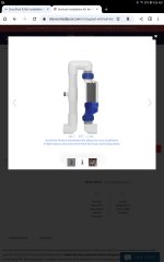
CircuPool RJ-60 Plus
I have one on order but while I am thinking through things, I want to make sure I am correctly accounting for how things currently run.

I have an electronic timer that sits between the electrical panel and all of the pool equipment. Basically, it allows my system to run every 30 minutes for 30 minutes or so (I think it is set to around 10 hours of runtime a day). So all of the equipment is switched on. Power is cut and once restored it all comes back to life, etc. My current SWG (that died) has a toggle on/off switch. Looking at the RJ60 it appears to be a button...

Question #1: If the RJ60 is on and running, and then say the power is cut (timer in this case), maybe a power outage in others, will it turn back on itself?

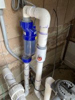
My piping area is small. It appears I might need to install it vertically.

Question #2: If I install it vertically, can it come right after a down 90? If not is there a minimum distance needed from the elbow to the cell? I will have to install the flow switch after the cell, but according to the manual, this should be fine.
 
If the RJ controller is powered on and power is cut to the unit, the controller will resume when power is restored. I use a timer to control my swg in this manner.
Concerning the vertical installation, the piping kit sold for vertical installation illustrates their suggestion for clearances.
 

Attachments

  • Screenshot_20230715-090607_Chrome.jpg
    Screenshot_20230715-090607_Chrome.jpg
    124 KB · Views: 15
#1 - Yes

#2 - you want 6-12" of straight pipe before the flow switch. The flow switch can be installed after the cell which is considered straight pipe, page 15, #5 of manual. Many here will advise not installing the flow switch in a down flow on a vertical pipe despite it being shown as an acceptable install on page 14. Their theory being if the spring fails, the the switch will fall due to gravity and default as open if flow stops. I counter that the flow switch paddle I was sent is plastic and in a pipe full of still, non flowing water, the paddle is naturally buoyant and would return, float to the off position. My switch is below the cell, in a vertical install as per the manual. Someone with a broken switch return can verify this is the case, perhaps CPool has already or will.
 
So with broken spring you think the plastic paddle will sink. Have you tested to confirm that it is negatively buoyant?
Yes. Specifically with an RJ-60...after I installed incorrectly in the downward position. After the test, I cut both sides out and switched it. PVC couplers where I cut and swapped.
 

Attachments

  • image.jpg
    image.jpg
    492 KB · Views: 14
Did your flow switch actually fail? Please be clear. Your origional install position was  not incorrect according to the CPool manual page 14. How did you make your determination. Again be clear, are you stating the CircuPool manual is incorrect and creating a possible dangerous condition with their product?
 

Enjoying this content?

Support TFP with a donation.

Give Support
Did your flow switch actually fail? Please be clear.
No.
Your origional install position was  not incorrect according to the CPool manual page 14. How did you make your determination. Again be clear, are you stating the CircuPool manual is incorrect and creating a possible dangerous condition with their product?
Please provide specific cite of the manual text you would like me to respond to...I have no idea what you are referring to...
 
If you have your CP manual turn to pages 14-15. Look at the several recommended installation diagrams on page 14 then read the specific instructions for installing the flow switch, page 15 line #5.
Your guidance sure seems to conflict with the manufacturers published instructions.
 
Nothing I have said contradicts what I read on page 15. If you are talking about my advice to put the switch in the upward flow of the water, that was in context of OP installing vertically.
 
While diagram #1 from the position of the pump can be assumed a top view, 2 and 3 are not labeled either way. I have reached out to CP for clarification and will update when I hear back. :cheers:
 
Thread Status
Hello , This thread has been inactive for over 60 days. New postings here are unlikely to be seen or responded to by other members. For better visibility, consider Starting A New Thread.