AquaRite r1.59 resetting Average Salt

chlorinatorpro

In The Industry
Feb 16, 2016
170
CA
Please refresh my memory - the AquaRite r1.59 board when resetting average salt reading, the relay clicks and we get 25V/6a on effort #1 but we when reset it a second time there is no click and we always get 31V and 0a and an instant salt reading of -0. A new cell is installed replacing a one year old cell and getting the same readings using either cell.

Does this sound like a board error or even more specifically a K1/K2 relay issue?
 
Last edited:
For AquaRite, move the switch from auto to off and check all of the readings.

Move the switch back to auto and recheck the readings.

Move the switch to off for a minute and then back to auto and recheck the readings.

Switching the unit off and then back on makes the unit reverse polarity.

Report all readings.

What are the first seven characters of the cell and box serial numbers?

What is the actual salinity and how are you measuring it?

What is the T-cell size?

Is the T-cell size set correctly in settings?

To get the performance percentage of the cell in each polarity, divide the instant salinity reading in each polarity by the actual salinity reading.

For example, if the instant reading is 3,300 ppm and the actual salinity reading is 3,300 ppm, then the salt cell is working at 100%.

However, if the actual salinity was 3,800 ppm, then the performance percentage is 86.8%.

Anything over 75% is acceptable.

At75%, or lower, in either polarity, it's time to consider replacing the cell.

The instant salinity in both polarities should be about the same (+/- about 200 ppm).

You need to be really sure about the actual salinity reading.

You need to use a K-1766 salt test kit or a calibrated meter.

K-1766 Taylor Salt Test

Note that ProLogic, AquaLogic and AquaPlus use the Hayward T Cell.

However, the procedure to get the diagnostic readings is different.

Here is the procedure for ProLogic, AquaLogic and AquaPlus:

Go to the diagnostic screen, note the readings and then press the + button to reverse the polarity.

When the new numbers appear, see what they are.

Then, press + again and note the new readings.
 
For AquaRite, move the switch from auto to off and check all of the readings.

Move the switch back to auto and recheck the readings.

Move the switch to off for a minute and then back to auto and recheck the readings.

Switching the unit off and then back on makes the unit reverse polarity.

Report all readings.

What are the first seven characters of the cell and box serial numbers?

What is the actual salinity and how are you measuring it?

What is the T-cell size?

the relay clicks and we get 25V/6a on effort #1 but we when reset it a second time there is no click and we always get 31V and 0a and an instant salt reading of -0.
I don't understand what you are talking about.

Why are you trying to reset the average salinity multiple times?

Can you provide the requested readings?

Even if you don't know why it's important, I do.
 
Push the diagnostic button until the instant salinity (ie, -3000) is on the display. Move the switch from Auto to Superchlorinate and then back to auto. All it does is replacing the number on the display with the instant salinity reading and nothing else! NO relay clicking is involved. Each time the switch is moved from OFF to Auto, the relay would click. If it does not click on the second try, grab a DVM. Measure if there is 24Vdc present across the relay coil, either K1 or K2.
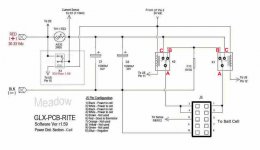
For the Aquarite, the two relays K1 and K2 are energized one at a time per cycle or by manually moving the switch from off to auto. To better understand how the polarity changes, please reference the schematic diagram in the below link. Try to visualize how the SPDT relay contact would switch between NO and NC or vice versa. Follow the trace connection going to J5 conn. Probe for dc voltage between pins 1 and 2 while moving the switch back and forth between off and auto. If the current is missing in one direction then you might have a bad relay or loose solder point or bad relay driver (U5), not likely! Next is to figure out which of the two relays is acting up! Stay focus on J5 conn, pins 1 and 2, figure out which polarity is missing against the Blk and Red terminals on the top right-hand corner of the pcb. Hope this helps!
 
  • Like
Reactions: chlorinatorpro
For AquaRite, move the switch from auto to off and check all of the readings.
2400
87
31.4
0.00
98p
-0
AL-1
r1.59
t-15

Move the switch back to auto and recheck the readings.
2400
87
26.2
5.65
98p
-2500
AL-1
r1.59
t-15

Move the switch to off for a minute and then back to auto and recheck the readings.
2500
87
31.4
0.00
98p
-0
AL-1
r1.59
t-15

Cell is brand new generic. Gives exact same readings for 1 year old generic.
Salt measures at 3200ppm using Taylor K-1766 and pool store test.
Do not know box s/n.
 
Probably a bad solder joint or relay.

I would remove the circuit board and check the back for obvious damage.

Touch up the bad solder point and retry.

If that does not work, you will probably have to replace the relay.
 
  • Like
Reactions: C0d3Sp4c3
Interesting! You can take care of the low instant salinity reading later.
Following the initial startup, the relay K1 will get energized while K2 remains de-energize. Moving the switch from Auto to OFF and back to Auto, K2 is energized while K1 is de-energize. And this is where you are having problems with, right? Don't forget, there is always a 10 seconds delay in between, before the polarity reverses.

Here's a detailed troubleshooting tips for you.
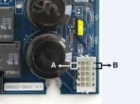
GLX-PCB-RITE_Pwr_Dist_Salt-Cell_r159.jpgAquaRite_Main_Board_Test_Points.jpg
1. Turn off the AC power to the pcb and disconnect the salt cell.

2. Grab a DVM and check the continuity between pins 1 (side B) and 2 (side A) on the J5 conn as shown in the pic.
a. Referencing the above schematic diagram, you may have noticed pins 1 and 2 on the cell connector is a closed loop circuit via the relay K1 (A/B) and K2 (A/B) point.
b. The DVM should read zero (0) Ohm. Anything else, inspect K1/B point (I'll explain later).

3. When the pcb is first turned ON, you'll hear the relay click post system passing the initialization period. Pin 1 (side B) on the cell connector goes Positive (31vdc)) while pin 2 (side A) is Negative for the duration of 180 mins cycle or until the set % output is reached.
a. Moving the switch from auto to off and back to auto will prompt the controller via sw to reverse the polarity. Pin 1 (side B) will become Negative while pin 2 (side A) is Positive (31vdc).
b. If you passed the continuity test in Step 2, exclude K1/B but inspect K2/C point for solder breaks. It could be a faulty K2 relay (coil/open) or hard stuck K2 A/B contact point or faulty U5 driver chip (not likely).

4. At anytime the pcb is powered ON, there is a constant 30-31vdc flowing at point C of the K1 & K2 relay via the thermistor. Point B is tied to the Negative via the R15 metal jumper.
a. K1 and K2 relay coil is energized one at a time via the U5 Latch driver which is sw driven. Allowing the current to flow to the cell and therefore, chlorine is produce.
b. K1 & K2 relay Coil connection: One side of the coil have a constant 24vdc from the output pin of (U7) 24V regulator. While the opposite end is tied to the latch driver (U5) which is sw driven. Pin 12 for K1 and pin 11 for K2 respectively.
c. The software via the Microcontroller instruct the U5 chip to pull down one side of the relay coil to the Negative post. Hence, the relay clicks.
d. Follow the pcb trace connections, check for continuity and /or inspect for hairline cut or breaks.
More to follow if the above Steps failed to solve the problem. Your call...:cheers:
 
Last edited:
Thread Status
Hello , This thread has been inactive for over 60 days. New postings here are unlikely to be seen or responded to by other members. For better visibility, consider Starting A New Thread.